Activity 2: Create construction geometry
In this activity, you modify the basic shape by creating construction geometry. After extruding the profile into a three dimensional body, you create additional construction geometry on one surface and add constraints.
Prerequisites
- Activity 1 is complete: the basic shape is sketched, constrained, and dimensioned.
Steps
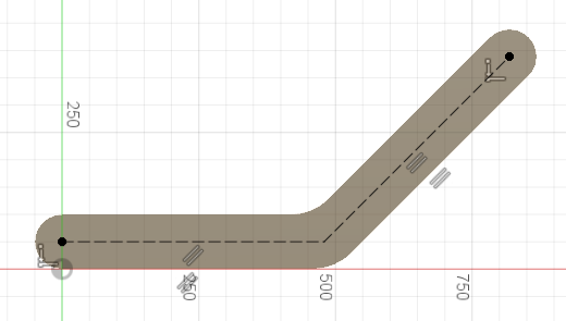
Round out the edges of the bracket using construction geometry and by creating circles.
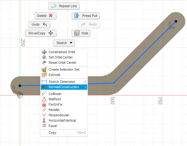
- To convert the end edges to construction geometry, select the upper edge, hold keyboard Shift, and select the lower edge. Right-click, and select Normal/Construction.
Note: Construction geometry is not considered when looking for profiles. Use construction geometry for reference when creating sketches. It will show as dashed lines to indicate it is construction geometry. - To sketch a circle profile at the lower end, select Sketch > Circle > Center Diameter Circle.
 Select the midpoint of the edge.
A midpoint constraint (triangle) appears.
Drag the circle to the edge. A Tangent constraint (square) appears to indicate alignment with the edge.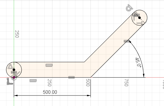
- Repeat at the top edge.
- To exit the tool, press keyboard Esc.
- To convert the end edges to construction geometry, select the upper edge, hold keyboard Shift, and select the lower edge. Right-click, and select Normal/Construction.
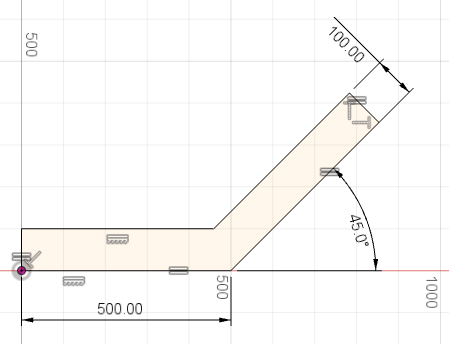
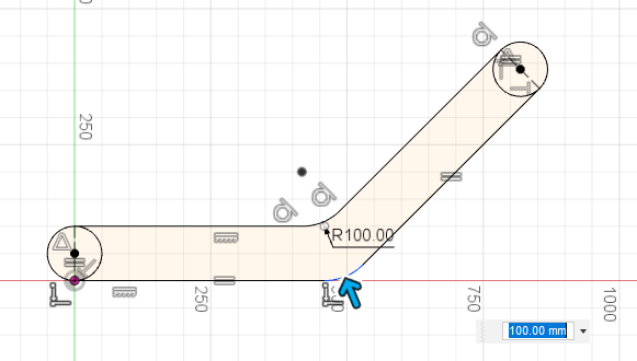
Create fillets at the intersection points.
- To create fillets, select Sketch > Fillet.
 Select the two intersection points.
 - Enter a value of 100 mm.
- To confirm, press keyboard Enter.
- To complete the sketch, click Finish Sketch
 .
.
Note: All fillets created at the same time will have an equal radius. Create them separately to have different radius values. In many cases creating a fillet in a sketch is not the best option; as you see here, it deletes the 500 mm dimension.- To create fillets, select Sketch > Fillet.
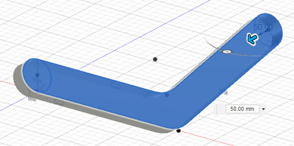
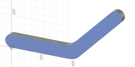
Extrude the profile into a body.
- To create a body from the sketch, select Modify > Press Pull
 .
. - Select the three profiles.
- To set the depth, drag the arrow or type in a value of 50 mm.
- To finish the tool, click OK.
Note: One sketch may contain multiple profiles. In this case, we limit the number of profiles through the use of construction geometry.
- To create a body from the sketch, select Modify > Press Pull
Create a sketch on one surface of the bracket, convert it to Construction geometry, and add constraints.
- To create a new sketch, select Create > Create Sketch.
 Select the top surface of the bracket.
- To sketch the lines, select Sketch > Line.
 Select the left center point. Select near the middle, and select near the upper center point. To exit the tool, press keyboard Esc.
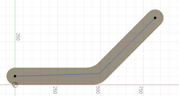
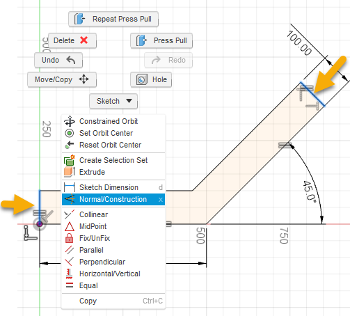
- To convert the two new lines to construction geometry, select the first edge, hold keyboard Shift, and select the second edge. Right-click and select Normal/Construction.
- To constrain the two construction lines, select the Parallel constraint.
 Select the two pairs: horizontal pair (line/edge) and the angled pair (line/edge).
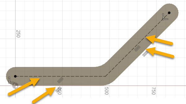
Note: This fully constrains the lines. The construction lines turn black when constrained.- To create a new sketch, select Create > Create Sketch.
Activity 2 summary
In this activity, you used construction lines to round out the two ends of the bracket, and you created fillets at the corners. You then extruded the sketch into a body and created a new sketch on one surface of the solid body.