Activity 2: Sketching to create round gear teeth
In this activity, you create round gear teeth inside a hollow cylinder. This requires you to:
Sketch a smaller circle using a center point and a diameter.
Apply a constraint and a dimension to the circle to control its size and position.
Create a circular pattern from the original circle.
Convert the cirlces in the circular pattern into 3D geometry.
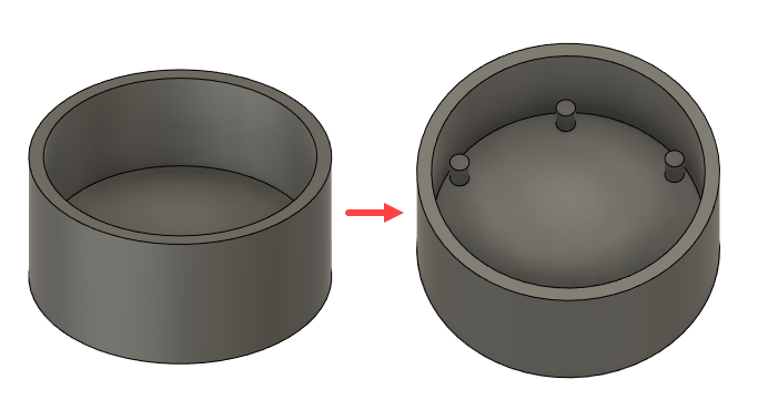
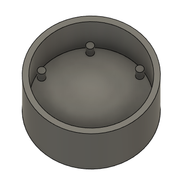
Completed round geer teeth inside the cylinder
Steps
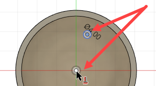
Start sketching a circle, with a 4 mm diameter, on top of the base of the cylinder.
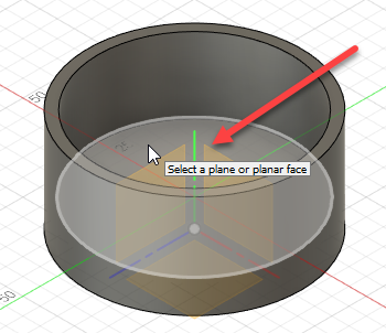
- Click Solid > Create > Create Sketch
 .
. - Select the top of the base of the cylinder as the plane you want to sketch on.
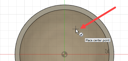
- Click Sketch > Create > Center Diameter Circle
 .
. - Click to select the center point of the circle.
- Drag the mouse to start creating a circle, and type 4 mm in the Diameter field.
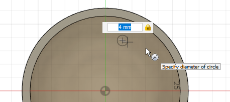
- Press Enter twice to complete the circle.
- Click Solid > Create > Create Sketch
Apply a Horizontal/Vertical constraint to the circle to align it to the center point of the face. This ensures that if the center of the face moves, the sketch moves with it.
- Click Sketch > Constraints > Horizontal/Vertical.
- Click the center point of the circle you just created, then click the center point of the face.
This aligns the two points.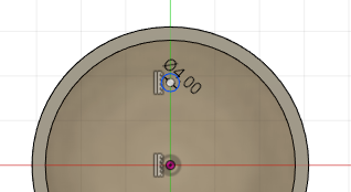
- Press Esc to finish applying the constraint.
Start sketching a circle, with a diameter of 25.4 mm, inside the hollow cylinder to use as the basis for the circular pattern.
- Click Sketch > Create > Sketch Dimension
 .
. - Select the center of the circle, and then the center of the face, as the objects you want to dimension.
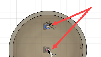
- Drag the mouse towards the right and click to place the dimension.
- Type 25.4 mm in the Dimension field.
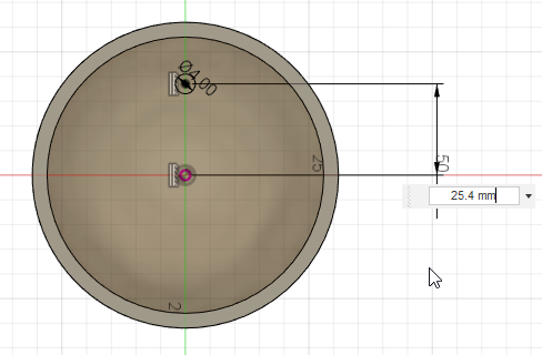
- Press Enter.
Note: The sketch 2D profile is shown in black to denote that it is fully defined; that is, it has been constrained and dimensioned.
- Click Sketch > Create > Sketch Dimension
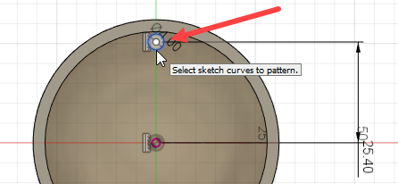
Create a circular pattern of six circles from the circle you have sketched.
- Click Sketch > Create > Circular Pattern . This displays the Circular Pattern dialog.
- Click Select next to the Objects field on the Circular Pattern dialog and select the circle.
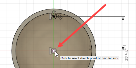
- Click Select next to the Center Point field and select the center point of the face.
- Type 6 in the Quantity field.
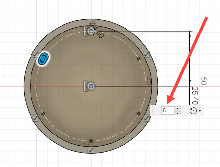
- Click OK on the Circular Pattern dialog to create the pattern.
- Click Sketch > Finish Sketch
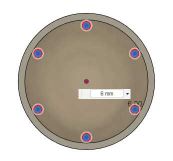
Extrude the circles in the pattern by a distance of 6mm to convert them into 3D features.
- Click Modify > Press Pull. This displays the Press Pull dialog.
- Click Select on the Press Pull dialog and then click each circle in turn to select all six circles. Selected circles are displayed in blue.
When you select a circle, the Extrude dialog is displayed. - Type 6 mm in the Distance field,then Click OK on the Extrude dialog.
- Use the ViewCube to orient the view to display the extruded features inside the cylinder.
Activity 2 summary
In this activity, you sketched a circular pattern and converted the circles into cylinders to create round gear teeth inside a hollow cylinder. To do this, you:
Sketched a smaller circle using a center point and a diameter.
Applied a constraint and a dimension to the circle to control its size and position.
Created a circular pattern of six circles from the original circle.
Converted the cirlces in the circular pattern into 3D geometry.
Completed round geer teeth inside the cylinder