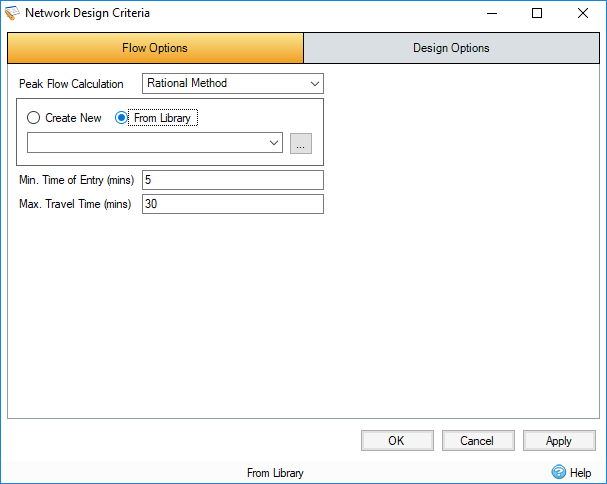
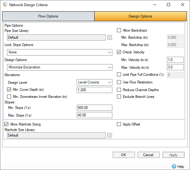
Flow and design options used by the Network Design can be modified on this form, rather than by running the wizard.
Flow Options
These parameters are used to determine the flow into the network.

Peak Flow Calculation
Select the calculation method to be used when sizing the pipes/channels. Choose from:
- Rational Method : Flow = Rainfall Intensity x Total Area + Total Base Flow
- (UK) Modified Rational Method: Flow = Rainfall Intensity x Total Area * Cr(1.3) + Total Base Flow
- Methode de Caquot: Flow is calculated via the Methode de Caquot equations which are considerably more involved that the Rational Method or (UK) Modified Rational Method equations. The method's inputs are the Caquot (Base and Advanced) parameters, selected Desbordes rainfall parameters and the Runoff Path Length and Catchment Slope of the Inflows upstream of the pipes belonging to the auto-sized Flow Path. Further information can be found on the Methode de Caquot page.
Rainfall Source
When Rational Method or (UK) Modified Rational Method is selected from the Peak Flow Calculation list box, the Rainfall Source list box lists the currently configured IDF curves and FEH, FSR, ARR, Desbordes, and Chinese Design rainfalls in the Rainfall Manager . When autosizing pipes/channels the rainfall intensity will be retrieved from the selected rainfall source based upon the Travel Time for the pipe/channel.
When Methode de Caquot is selected from the Peak Flow Calculation list box, the Rainfall Source list box lists only the Desbordes rainfalls configured in the Rainfall Manager.
In either case the parameters of the selected Rainfall Source are displayed below the Rainfall Source list box. In addition, if the Methode de Caquot is selected from the Peak Flow Calculation list box the Caquot Base Parameters and Use Shape Correction checkbox are displayed below the parameters of the selected Rainfall Source. To the right of the Base Parameters is a calculation button. Clicking this displays a separate form, which allows you to modify the Advanced Caquot parameters which in turn recalculates the Base Caquot parameters shown on the Network Design Criteria form.
Minimum Time of Entry
This is the minimum time that should be applied to the Time of Entry. It is the time it takes the rainfall falling on the catchment to reach the head of the line, which can be considered the Time of Concentration for the inflow area. This is added to the time of travel in the connection to produce an overall Time of Travel throughout the network as shown in the Network Design Report. This is required at the head of each branch line.
Maximum Travel Time
This allows the maximum travel time down the system to be capped at the given value. This prevents the intensity being used to size the pipe/channel reducing to low.
Design Options
These design parameters are used to guide the Network Design.

Pipe Options
This section includes the relevant fields to configure the Network Design.
Pipes Size Library - The Pipe Size Library is a sequential list of pipe diameters. New pipe libraries can be defined by clicking the button next to the box.
Lock Slope Options - Lock certain values of connections during sizing. The following options are available to lock:
- None
- Slopes
- Slopes and Invert Elevations
- Slopes and Crown Elevations
Design Options - Specify what should be minimized in the pipe sizing:
- Minimize Excavation - The pipes will be made bigger and try to avoid reducing the excavation of the pipes.
- Minimize Pipe Diameter - The pipes will be made lower and steeper, and will try to avoid sizing the pipes.
Design Level - Choose Level Crowns (Soffits) or Level Inverts from the list box to design the system with Level Crowns or Level Inverts respectively.
Minimum Cover Depth - The desired depth from the pipe crown/channel top to the cover elevation. When ground elevations have already been input, the program will warn you when the desired cover to ground elevation has not been achieved. When the option is turned on, the auto size calculation will attempt to redesign the system and achieve the above cover where it is feasible.
Minimum Slope - The desired minimum slope for a pipe/channel. This is desirable when the ground is flat or is sloping away from the pipes and minimum slopes are required to reduce excavation. When the option is turned on, the auto size calculation will attempt to redesign the system and achieve the minimum slope where it is feasible.
Maximum Slope - The desired maximum slope for a pipe/channel. This is desirable as laying connections too flat may result in blockages.
Allow Backdrops - Selecting this option will cause the Network Design to consider the backdrops between connections, and attempt to design within the minimum and maximum.
Minimum Backdrop - The desired minimum backdrop for a pair of connections, if a backdrop is below this, then it is lowered to 0.
Maximum Backdrop - The desired maximum backdrop for a pair of connections, if a backdrop is above this, then it is lowered to this value.
Check Velocity - Selecting this option will cause the Network Design to consider the velocity of each connection, and attempt to design within the minimum and maximum. In a Sanitary phase an additional combo box is available to pick the velocity method - Full Bore, 1/3 Proportional Velocity and (UK) 1/3 Proportional Velocity (Only available in UK region).
Full Bore - the connection full bore velocity is used when sizing against the minimum and and maximum velocity.
1/3 Proportional Velocity - the proportional velocity achieved by a connection with only 1/3 of the calculated flow is used when sizing against the minimum and maximum velocity.
(UK) 1/3 Proportional Velocity - the proportional velocity achieved by a connection with only 1/3 of the calculated flow is used when sizing against the minimum and maximum velocity and additional slope rules are applied (see link).
Minimum Velocity - The desired minimum velocity for a pipe/channel. The program will then choose a pipe diameter and slope with sufficient capacity to give the required Full Bore Velocity. When the option is turned on, the auto size calculation will attempt to redesign the system and achieve the minimum slope where it is feasible.
Maximum Velocity - The desired maximum velocity for a pipe/channel.
Limit Pipe Full Conditions - The amount of the pipe that is filled to be considered to "full ".
Use Flow Restriction - Selecting this option limits the base flow of any connection with a flow restriction, to that flow restriction.
Reduce Channel Depths - Selecting this option allows the Network Design to reduce channel depth and height by considering incoming connections to the channel.
Exclude Branch Lines - Selecting this option allows the Network Design to perform the pipe sizing only on the mainline.
Allow Manhole Sizing
This section includes the relevant fields to configure the Manhole Sizing. This checkbox controls if Manhole Sizing will take place by disabling the fields if unchecked.
Manhole Size Library - The Manhole Size Library is a list of multiple categories relating to the size of the manholes in relation to the connection and depth. As well as being used to determine the ladder protrusion, landing and benching width needed for offsetting.
Apply Offset - Selecting this option determines that offsets are required on any junction that meets the requirements. See Manhole Auto Size Calculations for more information on offsets and their requirements.