From the Run Manager Dialog Box, use the Fireflow Tab to conduct FireFlow Modeling Analysis. The Fireflow modeling process is a batch analysis of either all nodes with a fireflow demand assigned or all nodes within a domain with a fireflow demand assigned. The basic fire-flow analysis is a two-step process and it will automatically assign the fire-flow demand to each junction and solve for the residual pressure. Then it will set the residual pressure to the specified value and solve for the resulting flow. You can then determine the available pressure at the desired fireflow demand and the available flow at the minimum residual pressure.
Fire demand requirements can be specified based on the various types of building structure (e.g., single-family residential, multi-family residential, commercial, industrial, etc.) or other fire demand characteristic.
Based on the fireflows specified, InfoWater Pro calculates the maximum flow available at the hydrant while maintaining the user-specified residual pressure and, optionally, a maximum velocity constraint can also be applied.
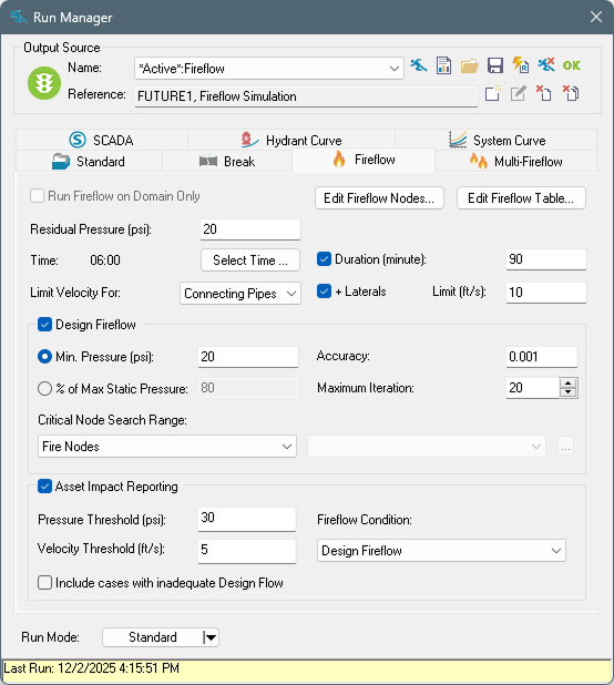
Run Fireflow on Domain Only
If checked, the fireflow analysis will be performed on the domain hydrants only.
Edit Fireflow Nodes
Opens the Group Edit function. See Group Editing-Fire-Flow.
Edit FireFlow Table
Opens DB Editor. See Fire Flow Demand Table.

Residual Pressure
The minimum residual pressure, usually 20 psi, targeted at each hydrant (junction node) in the modeled fireflow set. InfoWater Pro will calculate the maximum flow available at the hydrant while maintaining the user-specified residual pressure.
Time
The hydraulic time period at which the fireflow analysis will be calculated. A hydraulic simulation will be performed for all time steps up to and including the specified time period, where the fireflow simulation will be performed. Click
Select Time  to launch the
Select Time dialog box as shown below:
to launch the
Select Time dialog box as shown below:

Left click on the Status bar and move the bar to specify the Fireflow time step. Click OK to save and exit. Click Cancel to cancel and exit from the Select Time dialog box.
Duration
If this option is selected it allows you to extend the fireflow run over an extended time period from the defined fireflow instant. The duration entry in minutes is enabled only if the duration option is selected and the value entered is greater than zero. The module maintains the fireflow at the junction for the entire fire-flow duration. During this extended time period, the program will search for critical junction with the lowest pressure and the critical pipe with the highest velocity from the currently defined searching range. A separate report type “Fireflow Extended Time” will then be available from the Output Report Manager. The report highlights the critical conditions for this extended time run period.
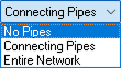
Velocity Limit
In addition to ensuring a minimum residual pressure at the hydrant, the available and design (see below) fireflow analyses can be constrained to avoid velocities at pipes to exceed a given value. The maximum available or design flow will be limited so that velocities at selected pipes do not exceed the value entered in the Limit text box. Select which set of pipes to constraint by selecting the desired option from the drop-down menu. The choices are No Pipes, Connecting Pipes (adjacent to each hydrant), or Entire Network (all pipes). Additionally, the velocity at virtual lateral pipes can be limited by enabling the + Laterals option. The diameter of the virtual laterals for each hydrant can be entered by clicking on the Fireflow Table button.
Design Fireflow
Minimum Pressure
When checked, InfoWater Pro determines the design flow (or the maximum flow available) from each junction node being simulated such that pressure within the Critical Node Searching Range does not drop below the minimum design pressure specified.
% of Max Static Pressure
When checked, InfoWater Pro determines the design flow (or the maximum flow available) from each junction node being simulated such that pressure within the Critical Node Searching Range doesn't drop below the specified percent of the maximum static pressure under regular demand conditions.
Accuracy
This is the convergence criterion used to determine if a solution has been found for the design fireflow. Trials end when the sum of all flow changes divided by the sum of all link flows is less than this number. The suggested value is 0.001.
Maximum Iteration
Maximum number of hydraulic simulations allowed to find the value of the design fireflow. The suggested value is 40.
Critical Node Searching Range
Used to specify which nodes will be evaluated for minimum pressures during the fireflow simulation. Choose one option from the following: Fire Nodes, Entire Network, Selection Nodes, and Domain Nodes.

The domain option will be available only when a domain has already been created.
Selection Nodes
This allows you to choose a selection set from the drop-down list.
Asset Impact Reporting
Select this option to create junction- and pipe-centered reports summarizing the hydraulic effect of fireflow demand. While regular reports organize by hydrant, asset impact reports identify locations with the largest service disruptions or assets with the most limited hydraulic capacity.
Pressure Threshold – This pressure is used to count warnings for each junction whenever the pressure falls below the threshold during the selected fireflow condition.
Velocity Threshold – This velocity is used to count warnings for each pipe whenever the velocity exceeds the threshold during the selected fireflow condition.
Fireflow Condition – This option selects the type of fireflow used at each hydrant to report for all junctions and pipes.
Include cases with inadequate Design Flow – Check this option to include hydrant cases where the design fireflow value fell below the required fireflow.
Run Mode
Used to control how the run is managed. Select from the following options from the drop-down menu:

- Standard - This will cause the simulation to occur within the user interface. It is the fastest for quick runs, but the interface will be unresponsive until the simulation is complete.
- Background - This option will run the simulation in the background of the local machine. This allows ongoing interaction with the model as the simulation is in progress.
- Cloud - This option will parallelize the fireflow analysis in the cloud, offering the fastest performance for analysis of many hydrants at once.
Notes:
- At this time, cloud fireflow simulations will only return the summary Fireflow and Fireflow Desing output tables. Any user selection to generate model output in the Fireflow Demand table will be ignored.
- Sending simulations to the cloud will add a few seconds of overhead time before parallelization occurs. InfoWater Pro will recommend fast/small simulations to remain on the local machine automatically and notify in the message board.
- The accelerated solver for design fireflow is used by default. The legacy solver can be used instead in the Advanced Simulation Options. However, asset impact reporting and enforcing velocity constraints on virtual laterals necessitate the use of the accelerated solver.
Results
Learn more about Fireflow Run Results in the Report Manager.