After extracting shapes and before creating a nest, you can customize properties for the shapes in your nest.
Open the Source Nesting Properties Dialog Box
- Click
Nesting Properties
 on the
Inventor Nesting ribbon.
on the
Inventor Nesting ribbon.
The Source Nesting Properties dialog box opens. It contains a table of your shapes and their associated properties.

Non-editable values are highlighted in gray. Values that you change from the default are highlighted in orange. (Some values cannot be changed unless you deselect Bind.) The total number of shapes listed is shown in the upper right corner.
- To reset a row to the default values for a material at any time, right-click the row and select Reset to Material Properties.
Change Shape Priority and Orientation
Each material has default orientation settings that are defined in the Process Material Library dialog box. You can deviate from these in the Source Nesting Properties dialog box for each shape that will be nested. You can change the orientation before the nest is calculated, or set allowable options that can be used during calculation for optimal material use.
To change the shape orientation before the nest is calculated:
- To change the nesting priorities for the shapes, enter values in the
Priority column.
This specifies the order in which nesting places the parts on the sheet. Inventor Nesting uses this first, then part size. A part with a higher priority number nests before a part with a smaller value, regardless of efficiency.
- Select or deselect
Mirror.
With Mirror enabled, the shape is flipped along its Y-axis.
- Enter a value under
Orientation.
This is the same as the Material Grain setting in the Process Material Library. It creates an angled grain for the part by offsetting the shape from the natural layout angle of the material.
To change allowable orientation options that can be used to optimize the nest while it is calculated:
- Deselect
Bind in the appropriate row.
Note: Normally you should leave Bind selected, but deselecting it enables you to override these parameters as defined in the Process Material Library. If at some point if you modify these settings in the Process Material Library, the changes will not be reflected here unless you re-select Bind. See About Binding.
- Select or deselect
Pre-Kit.
Designate parts that can be "kitted" together to count as one part in a nest.
 Pre-Kit is available with
Inventor Nesting Update 2019.3 and later.
Pre-Kit is available with
Inventor Nesting Update 2019.3 and later.
- Adjust orientation values.
- Rotate (90, 180, 270): Allow the shape to be rotated by selected 90-degree presets.
- Deviation: Allowable deviation from the presets; for example, if you enter 10, a 90-degree orientation is allowed to deviate between 80 and 100.
- Increment: Allowable deviation increments. For example, if you enter 2, a 10-degree deviation can occur in increments of 2; that is, 2, 4, 6, 8, and 10.
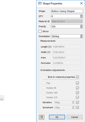
Edit Shape Properties from the Browser
- In the
Inventor Nesting browser, expand Geometry Sources to find the shape whose properties you want to edit.
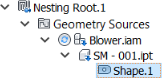
- Right-click the shape in the browser and select Properties.
The shape Properties dialog box opens. It contains the same properties available in the Source Nesting Properties dialog box. Edited values that differ from material defaults are highlighted in orange.