Standard Steel Sections
On this tab, you can select sections from a database.
| Properties | Description |
|---|---|

|
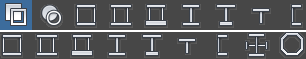
Available section shapes. Click an icon to filter the Family list. If you click the
 All icon, the Family list displays all section families. If you click a different icon, the list is filtered to display the several families represented by the icon. The image illustrates the shape of sections represented by the icon. All icon, the Family list displays all section families. If you click a different icon, the list is filtered to display the several families represented by the icon. The image illustrates the shape of sections represented by the icon.
|
| Material | Steel grade associated with a section.
Depends on the section type. The Material list displays a list of materials from databases set for your project in the Job Preferences dialog. |
| Gamma angle | It is a rotation angle that you assign to the section of a linear element. For most sections, the default value is 0. |
| Label | Name of a section. You can use a standard label assigned automatically, such as, W 16x40. |
| Color | Color for displaying a section. |
| Database | The list includes the databases set for your project, in the same order as in the Job Preferences dialog. |
| Family | The list displays section families. You can filter it by selecting one of the icons. |
| Section | Section from the database. |
| Variable | Use this option to define a section that is variable along the element length. It is active only for some section types, such as I-sections and tubes. After you select Variable, enter a value of the section dimension, such as section height for I-sections, or section diameter for tubes. This dimension is automatically added to the section label. This way you define a section with the standard properties at its beginning, and with the properties that you entered at its end. The section height or diameter changes linearly along the element length. Other dimensions of the section do not change. |
| Elasto-plastic analysis | By default, it is disabled (a section is an elastic section). To specify parameters of elasto-plastic analysis, select the check box. Then click the button. It opens the Elasto-plastic Parameters dialog. |
Parametric Steel Sections
On this tab, you can define a section by specifying section dimensions.
 |
Available section shapes. Click an icon to update the Dimensions panel. Then it displays fields appropriate to the section shape that you select. The image illustrates the shape and dimensions of a section represented by the icon. |
| Material | Steel grade associated with a section.
Depends on the section type. The Material list displays a list of materials from databases set for your project in the Job Preferences dialog. |
| Gamma angle | It is a rotation angle that you assign to the section of a linear element. For most sections, the default value is 0. |
| Label | Name of a section. You can use a standard label assigned automatically, such as, RECT_1. |
| Color | Color for displaying a section. |
| Dimensions | Section dimensions are illustrated in the image. |
| Solid | Available under Dimensions, for rectangular and tube sections. Select it to add a section filled inside. |
| n | Available for
 polygonal sections. Number of sides for the polygon polygonal sections. Number of sides for the polygon
|
| D | Available for polygonal sections. Tip to tip diameter. It is a diameter of a circle circumscribed on the outer polygon contour |
| d | Flat to flat diameter. It is a diameter of a circle inscribed in the outer polygon contour. |
| Elasto-plastic analysis | By default, the model of steel material is linearly-elastic. To specify properties of the elasto-plastic model of steel material, select the check box and click the Elasto-plastic analysis button. It opens the Elasto-plastic Parameters dialog, where you can specify parameters for the elasto-plastic analysis. |
Tapered Steel Sections

|
Available section shapes. Click an icon to update the Dimensions panel. Then it displays fields appropriate to the section shape that you select. The image illustrates the shape and dimensions of a section represented by the icon. |
| Material | Steel grade associated with a section.
Depends on the section type. The Material list displays a list of materials from databases set for your project in the Job Preferences dialog. |
| Gamma angle | It is a rotation angle that you assign to the section of a linear element. For most sections, the default value is 0. |
| Label | Name of a section. You can use a standard label assigned automatically, such as, RECT_V_1. |
| Color | Color for displaying a section. |
| Dimensions | Section dimensions are illustrated in the image. |
| Start or Origin | Dimensions at the beginning of the section. |
| End | Dimensions at the end of the section. |
| Solid | Available for rectangular and tube sections. Select it to define a section filled inside.
After you select this option, the edit fields for specifying t wall thickness are inactive. |
Compound Steel Sections
On this tab, you can define compound sections, that is sections composed of two or more chords connected by a batten or lattice.

|
Available section shapes. Click an icon to update the Dimensions panel with fields appropriate to the section shape that you select. The image illustrates the shape and dimensions of a section represented by the icon. |
| Material | Steel grade associated with a section.
Depends on the section type. The Material list displays a list of materials from databases set for your project in the Job Preferences dialog. |
| Gamma angle | It is a rotation angle that you assign to the section of a linear element. For most sections, the default value is 0. |
| Label | Name of a section. You can use a standard label assigned automatically, such as, 2 C 3x3.5 or 4 L 2x2x0.125.
Note: Specify labels so that they contain information about the sections from which the chords are made. This information is important for the design of compound sections.
|
| Color | Color for displaying a section. |
| Database | The list includes the databases set for your project, in the same order as in the Job Preferences dialog. |
| Family | The list displays section families. You can filter it by selecting one of the icons. |
| Section | Section from the database. |
| Spacing d | Distance back to back between components of a compound section. Click
 to disable the spacing field. Then chords of a compound section are connected to each other by a weld (spacing = 0). to disable the spacing field. Then chords of a compound section are connected to each other by a weld (spacing = 0).
|
|
Face to face
Back to back |
Available when you select
 Two C- sections and C-section and I-section. Use these options to position sections with respect to each other: Two C- sections and C-section and I-section. Use these options to position sections with respect to each other:
|
|
Shorter legs back to back
Longer legs back to back |
Available when you select
 Two angles back to back. Use these options to position angles with respect to each other: Two angles back to back. Use these options to position angles with respect to each other:
|
|
Shorter legs
Longer legs |
Available when you select
 Two angles face to face. Use these options to position angles with respect to each other: Two angles face to face. Use these options to position angles with respect to each other:
|
| Other dimensions and settings | All parameters and settings specific to individual compound sections are illustrated in the image on the Compound tab. |


Special Steel Sections
On this tab, you can define corrugated, castellated, and welded sections.

|
Available section shapes. Click these icons to select a section shape. Then fields in the Dimensions panel are updated to include dimensions and settings appropriate for the selected section. The image illustrates the shape and dimensions of a section represented by the icon. |
| Material | Steel grade associated with a section.
Depends on the section type. The Material list displays a list of materials from databases set for your project in the Job Preferences dialog. |
| Gamma angle | It is a rotation angle that you assign to the section of a linear element. For most sections, the default value is 0. |
| Label | Name of a section. You can use a standard label assigned automatically. |
| Color | Color for displaying a section. |
| Database | Available for SFB, IFBA, and IFBB sections. The list includes the databases set for your project, in the same order as in the Job Preferences dialog. |
| Family | Available for SFB, IFBA, and IFBB sections. The list displays section families. |
| Section | Section from the database. |
| Other dimensions and settings | All parameters and settings specific to individual special sections are illustrated in the image on the Special tab. |
Steel Sections Specified by Ax, Iy, Iz
On this tab, you can define a section by specifying its structural properties.
| Material | Steel grade associated with a section.
Depends on the section type. The Material list displays a list of materials from databases set for your project in the Job Preferences dialog. |
| Gamma angle | It is a rotation angle that you assign to the section of a linear element. Not available on the Ax, Iy, Iz tab. |
| Label | Name of a section. You can use a standard label assigned automatically, such as Section1. |
| Color | Color for displaying a section. |
| Structural properties of a section | To specify a section, define at least: Ax, Iy, and Iz. |
| Additional parameters | Click this button to open the Additional Parameters dialog. There you can specify properties for analysis of internal stresses and code-checking. Values of properties that you define in this dialog are used in the design of steel and timber structure elements. |