Learn how to define types and values of loads for particular load cases.
- Continue working in your project, or open the project
Tutorial_Alpha_Load_Cases.rstructure.
Note: To open the project, click Explore Tutorials from the Welcome Screen or navigate to the Tutorials folder C:\Users\Public\Public Documents\Autodesk React Structures Tech Preview\Tutorials.
- Click
Loads
 Surface
 Uniform Surface Load.
The Uniform Surface Load dialog opens.
- Add a
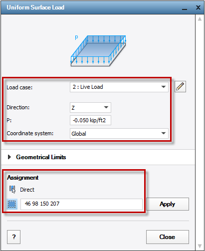
Live Load by setting the following parameters:
- Load case: Live Load
- Direction: Z
- P: -0.050 kip/ft2
- Coordinate system: Global.
- Click
 and use the Selection mode to assign the load to model elements.
- Select model elements using either of the following ways:
- In the active selection box, enter the floor numbers: 46 98 150 207.
- In the drawing area, select all floors except the floor from the top story.
or
The Uniform Surface Load dialog looks as follows.
- Click
Apply
to apply the load to the selected floors.
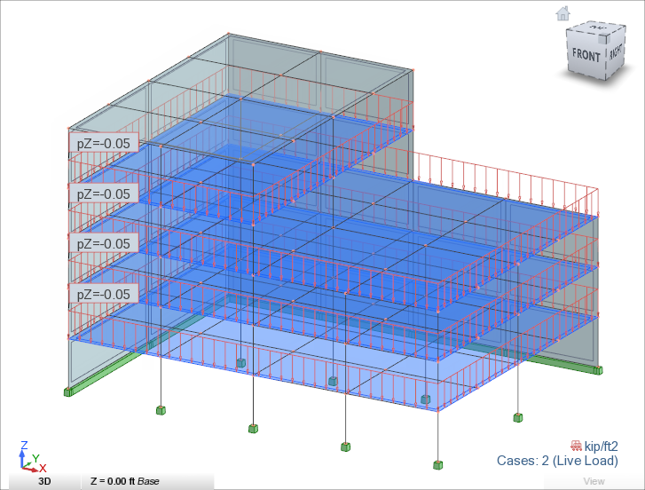
The Live Load contour displays in the model view.
- Add a
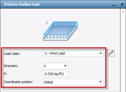
Wind Load by setting the following parameters:
- Load case: 3: Wind Load
- Direction: X
- P: 0.020 kip/ft2
- Coordinate system: Global.
- In the drawing area, right-click and select
Rotate 3D from the context menu.
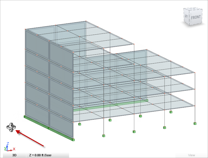
The Rotate 3D icon displays in the drawing area.
- In the drawing area, left-click and hold the button to rotate the view to the left side of the building.
- In the Uniform Surface Load dialog, click
 Direct to assign the load to elements.
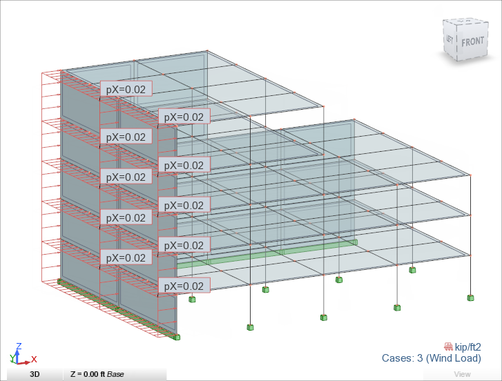
- In the drawing area, select all walls located in the Y direction to apply the load to the surface elements.
The Wind Load contour displays in the model view.
- Click the
Go Home icon of the ViewCube to display the default view of the model.
- Add a
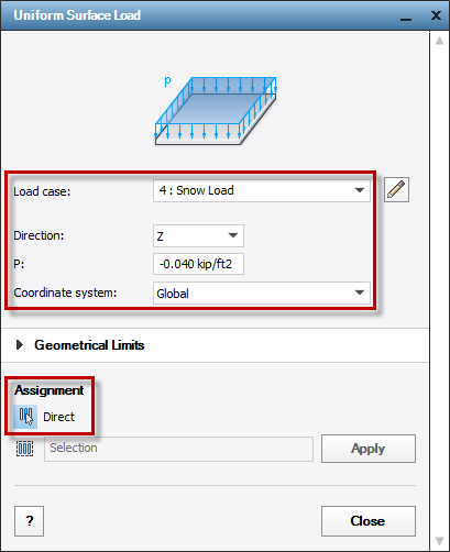
Snow Load by setting the following parameters:
- Load case: 4: Snow Load
- Direction: Z
- P: -0.040 kip/ft2
- Coordinate system: Global.
- Click
 Direct to assign the load to elements that you select directly in the drawing area.
The Uniform Surface Load dialog looks as follows.
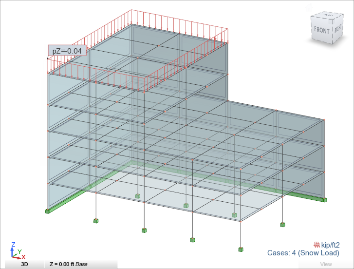
- In the drawing area, select the floor on the top story.
The Snow Load contour displays in the model view.
- Close the Dialog organizer.
- In the status bar, click
 (Load symbols) and
 (Load value descriptions) to display the load symbols and the load descriptions.
Note: For more information about the status bar, see User Interface.
 - In the Load Case drop-down list above the Object Inspector, select
Live Load to verify the defined load.

- Repeat this step for all defined loads.
- Save the project as Tutorial_Alpha_Loads.rstructure.