Learn how to create an axis grid to help you draw structural elements.
- Continue working in your project, or open the project
Tutorial_Alpha_Sections.rstructure.
Note: To open the project, click Explore Tutorials from the Welcome Screen or navigate to the Tutorials folder C:\Users\Public\Public Documents\Autodesk React Structures Tech Preview\Tutorials.
- Click
Model
 Datum
Datum
 Axis.
Axis.
The Axis panel displays in the ribbon.
- In the status bar, click
 (Grid) to display the modeling grid.
The grid displays in the drawing area.
Note: For more information about the status bar, see User Interface. - In the dynamic input tooltip, specify the first point of the
Axis 1:
- Enter the 0.00 absolute coordinate in the x: input box, press Tab,
- Enter the 0.00 absolute coordinate in the y: input box, press Enter.
Note: For more information about the dynamic input tooltip, see About Using Dynamic Input Tooltips. - In the dynamic input tooltip, specify the next point of the
Axis 1:
- Enter the 0.00 relative coordinate in the dx: input box, press Tab,
- Enter the
90.00 relative coordinate in the
dy: input box, press
Enter.
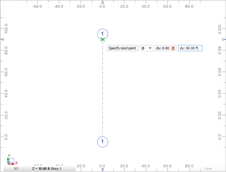
The Axis 1 displays in the drawing area.
- In the dynamic input tooltip, specify the distance to the
Axis 2:
- Enter the
20.00 value in the
D: input box, press
Enter.

The Axis 2 displays in the drawing area.
- Enter the
20.00 value in the
D: input box, press
Enter.
- Press Enter three times to draw the Axes 3, 4, and 5.
- Press Esc to finish defining the vertical axes.
- Click
View View
 Zoom All.
The axes rescale and are fully contained by the active view.

- Click
Model Axis and then enter
A in the Name box.
It specifies the name of the first horizontal axis.
- In the dynamic input tooltip, specify the first point of the
Axis A:
- Enter the -20.00 absolute coordinate in the x: input box, press Tab,
- Enter the 15.00 absolute coordinate in the y: input box, press Enter.
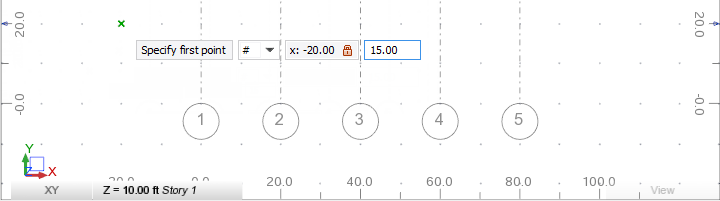
The first point of the Axis A displays in the drawing area.
- Press Down Arrow to change the input box, and then select Absolute # from the drop-down menu.
- Press Enter to switch to absolute coordinates.
- In the dynamic input tooltip, specify the next point of the
Axis A:
- Enter the 100.00 absolute coordinate in the x: input box, press Tab,
- Enter the 15.00 absolute coordinate in the y: input box, press Enter.
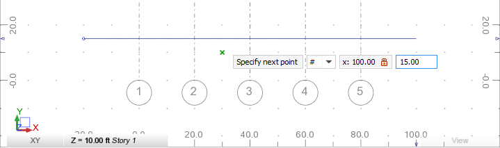
The Axis A displays in the drawing area.
- In the dynamic input tooltip, specify the distance to the
Axis B:
- Enter the 15.00 value in the D: input box, press Enter.
The Axis B displays in the drawing area.
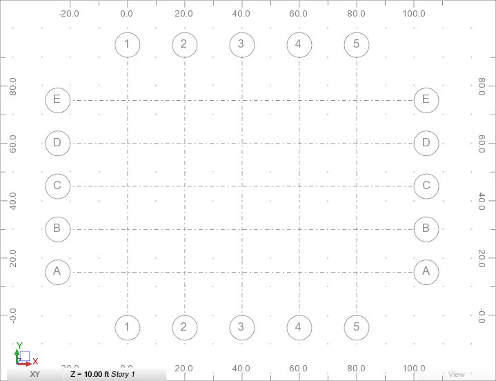
- Press
Enter three times to draw the
Axes C,
D, and
E.
The axes display as shown below.
- Press Esc twice to exit the tool for defining axes.
- In the Object Inspector, click
 next to
Grid axes to expand the list of axes.
Note: For more information about the Object Inspector, see Object Inspector.
next to
Grid axes to expand the list of axes.
Note: For more information about the Object Inspector, see Object Inspector. - Select
Axis A, and then in the Properties Pane select
Yes from the Highlight drop-down menu.
 Note: For more information about the Properties Pane, see Properties Pane.
 - Repeat step 19 for the
Axis C and
Axis E.
The axes highlight as shown below.

- Save the project as Tutorial_Alpha_Axes.rstructure.
For more information about structural axes, see Structural Axes.