Create a point on a surface to use as a reference for creating plies and analyses of a model. After you create the point, you must project it to be part of the surface, unless its only purpose is to be used as a laser target. A point is defined by Cartesian coordinates. You can also create points to be used as laser targets; these types of points do not need to be projected onto a surface.
A point and projection can be created in many different places in the TruPlan browser, including under:
- Geometry nodes
- Ply nodes
- Strategy nodes
Autodesk recommends that you create a folder in the browser specifically for storing points and projections; for example, a Points subfolder under the Geometry folder. To do this:
- Right-click a location inside the TruPlan browser.
- Select Add Folder from the context menu.
Once you create points, you cannot reorder them inside the browser.
You can also create curves (sketches) from the host application (for example, Inventor). A curve is necessary when using Guide Curve Offset propagation mode for fiber placement. Curves also need to be projected onto a surface.
You can edit points, curves, and projections by double-clicking them in the TruPlan browser.
Create a Point
- In the
TruPlan browser on the left side of the Inventor window, browse to the object where you want to create the point.
For example, you might want to create a geometry folder for this purpose.
- Click
Point
 on the
TruPlan ribbon.
on the
TruPlan ribbon.
The Point dialog box opens.
- In the Inventor window, click on or near the object where you want to create the point.
The coordinates of the point are shown in the Point dialog box, and a preview of the position of the point is shown in the application window.
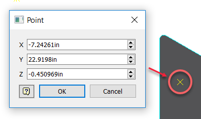
- Adjust point values or click different locations in the window to change the location where the point will be created.
- Click OK to fix the point in the position you want.
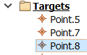
The point is created along with a new entry in the TruPlan browser in the location you selected.
Create a Curve
You can create a curve (sketch) in the Inventor 3D Sketch environment, then return to TruPlan to assess the design.
- Select a folder in which to creat the curve in the TruPlanbrowser.
- Click
Curve
 on the
TruPlan ribbon.
on the
TruPlan ribbon.
The Inventor 3D Sketch ribbon opens.
- Create your sketch using the tools on the Inventor 3D Sketch ribbon.
Tip: When you do this, the Inventor window does not show the STL file you are working on in TruPlan. To give yourself a reference upon which to create the sketch, you can import the STL file so that it shows in the Inventor Window. (In Inventor, click .)
- Click Finish Sketch on the 3D Sketch ribbon.
Your sketch opens in the TruPlan tab and is removed from the 3D Sketch ribbon. You need to project it onto a surface so that you can use it in TruPlan.
Project Geometry onto a Surface
- Click
Project
 on the
TruPlan tab of the Inventor ribbon.
on the
TruPlan tab of the Inventor ribbon.
The Projection dialog box opens.
- Click the
Projected selection arrow
 .
.
- Select a point or curve (sketch) to project.
- To select multiple items, hold down the Ctrl or Shift key while repeating the two previous steps.
- Select the surface geometry to which you want to project the selection.
- The Projection dialog box now shows that a support surface has been selected.
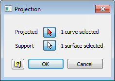
- Click OK to close the Projection dialog box.
- Right-click the point in the TruPlan browser and select Update. (Not necessary if automatic updates are enabled.)