Once you create the base view, you can generate several types of section views
- Full section views
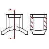
A full section view cuts through a part along a work plane. To specify the section plane for the full section view, at least a base view must exist.
- Aligned section views
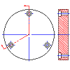
An aligned section view cuts through a part along two non parallel work planes. To specify the two section planes for the aligned section view, at least a base view must exist.
- Breakout section views
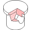
A breakout section view is used in drawings to remove material partially to reveal details behind it. You need at least a base view and another orthogonal view, one to specify the cut line and the other to indicate the depth.
Once you generate the breakout section view, the cut line hides. If you want to specify a new cut line or modify the existing cut line, use the AMEDITPSCUTLINE command to make it visible.
- Offset section views
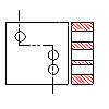
By offsetting or bending the cutting plane, an offset section view shows the features of an object that do not lie in a straight line. To specify the offset cut line, at least a base view must exist.
- Radial section views
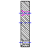
A radial section view rotates an auxiliary section view about a point in the parent view to make it appear like an orthographic section view. To specify the pivot point and cutting plane, at least a base view must exist.