
You can use the options on the Label Style Annotation tab to specify how the object information is displayed in the label.
To set label style annotation properties
- Select a label, and click
 .
.
- In the Label Style dialog box, click the Label Style Annotation tab.
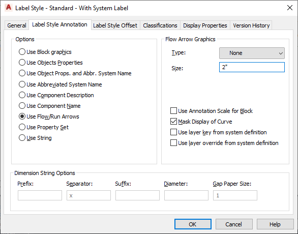
- From the Options list, select one of the following options:
Option Description Use Block graphics Use a specific block. You can also specify a scale factor to apply to the block.
If you want the block to scale accordingly when the annotation scale changes, select Use Annotation Scale for Block.
Note: The Use Annotation Scale for Block setting, not the Annotative property in the selected block definition, determines whether the label curve style is annotative. For more information, see Scaling Annotation.Use Objects Properties The properties displayed in the label are different for different objects in AutoCAD MEP 2025 toolset. The ID is displayed for schematic symbols, the designation is displayed for schematic lines, and the properties of the closest connector are displayed for MvParts.
For mechanical objects, specify a prefix, suffix, and symbol to display with the dimensions of duct, pipe, and duct and pipe fittings.
For electrical objects, specify a prefix, suffix, and symbol to display with the dimensions of cable tray, conduit, and cable tray and conduit fittings. For wire, the panel name is displayed if there is a home run, otherwise the circuit number is displayed. The ID is displayed for devices, and the panel name is displayed for panels.
For plumbing objects, specify a prefix, suffix, and symbol to display with the dimensions of plumbing lines and plumbing fittings.
Use Object Properties and Abbreviated System Name Displays both the object properties and the abbreviation assigned to the system definition for objects except devices, panels, MvParts, and schematic symbols and lines. For devices, panels, and MvParts, the abbreviated system name of the closest connector is displayed. For schematic symbols and lines, the assigned system label is displayed.
Use Abbreviated System Name Displays the abbreviation assigned to the system definition for objects except devices, panels, MvParts, and schematic symbols and lines. For devices, panels, and MvParts, the abbreviated system name of the closest connector is displayed. For schematic symbols and lines, the assigned system label is displayed.
Use Component Description Specify that the object style description be displayed. You can define the description on the General tab in the object style properties dialog box. To open the style properties dialog box, select the object, right-click, and select Edit (Object) Style.
Use Component Name Specify that the name of the component be displayed. You can define the object name for duct and pipe custom fittings, wire, devices, panels, and schematic symbols and lines on the General tab in the style properties dialog box for the object. To open the style properties dialog box, select the object, right-click, and select Edit (Object) Style.
Use Flow/Run Arrows Specify the flow/run direction by an arrow. Flow/run arrows are displayed as block graphics. You can choose that type of block graphic to display.
If you would like to use a custom flow/run arrow style that you created, select Use Arrow for Type of flow/run arrow, and then select the style from the Select Custom Arrow Block dialog box.
If you want the flow arrow graphics to scale accordingly when the annotation scale changes, select Use Annotation Scale for Block.
Note: The Use Annotation Scale for Block setting, not the Annotative property in the selected block definition, determines whether the label curve style is annotative. For more information, see Scaling Annotation.Use Property Set Specify a specific property set to display. Select a property set definition for the object, and specify a property set to display in the label.
Note: If the object does not have property sets assigned to it, you need to add the property set definitions to the object from the Properties palette, or by tagging the object.Use String Display a specific string of text.
- Select Mask Display of Curve to hide the centerline of the curve.
- Specify Dimension String Options. Note that some options may not be available depending on the label option selected in a previous step:
If you want to… then enter a value in… insert text before the variable Prefix separate to variables Separator insert text after the variable Suffix insert marks for an AutoCAD control code, such as %%c, (For more information, see Control Codes and Special Characters.) Diameter change the distance between the beginning of the curve display and the beginning of the text (if the text intersects the curve) Gap Paper Size