
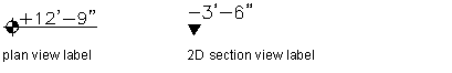
You can add elevation labels to your drawings. Elevation labels are useful when creating construction documentation. Adding elevation labels to your drawing helps the building contractor verify that the elevation of the segment or run meets the slope requirements of the building systems. Elevation labels are accessed from DesignCenter. You can drag the elevation symbol from DesignCenter into your drawing, and select the segment to which you want to apply the elevation label. The elevation is read from the properties of the segment. If the elevation label displays the wrong elevation, then you should verify that your object is positioned correctly.
Elevation labels
To add elevation labels
- Click
 drop-down .
- Click the AEC Content tab
- In the left pane, expand Documentation Elevation Labels, and select the desired subdirectory.
- In the right pane, select the elevation label that you want to add.
- Drag the elevation label from DesignCenter into your drawing.
- Select the object in your drawing to which to apply the elevation label.
If you want to use an elevation symbol repeatedly, drag the elevation label from DesignCenter directly onto a tool palette to create an elevation label tool.