This subassembly is a generalized solution to closing the sections from the outside edge of roadway to cut or fill intercept point.
It provides a variety of solutions for cut and fill conditions, as described below. Based on the input parameters provided, it first attempts to build a cut section. If unable to do this it builds a fill section instead. The final daylighting link can be omitted for cases where the corridor model needs to be left in an incomplete state. For example, this might be done so that grading surfaces on adjacent properties can tie to the hinge point on the uncompleted roadway.
You can also specify optional lined materials for daylight and other links (All Links, Daylight Links, Fill Links Only, and None).
Attachment
The DaylightGeneral subassembly is typically attached to the subassembly used at the outside edge of the roadway, such as the edge of shoulder, back of sidewalk, or back of curb. The attachment point is at the inside edge of the first Cut link, first Fill link, or Guardrail widening link.
Input Parameters
Note: All dimensions are in meters or feet unless otherwise noted. All slopes are in run-over-rise form (for example, 4 : 1) unless indicated as a percent slope with a “%” sign.
|
Parameter |
Description |
Type |
Default |
|---|---|---|---|
|
Side |
Specifies which side to place the subassembly |
Left / Right |
Right |
|
Include Daylight Link Omit Daylight Link |
Include or omit the Daylight link. |
Include / Omit |
Include |
|
Cut Test Point |
Number of the Cut Link whose outside end is the test point for determining if the section is in cut or fill |
Numeric, positive, integer |
3 |
|
Cut 1 Width |
Width of link Cut 1 |
Numeric, positive |
0.0 |
|
Cut 1 Slope |
Slope (x : 1) of link Cut 1 |
Numeric |
0.0 |
|
Cut 2 Width |
Width of link Cut 2 |
Numeric, positive |
0.0 |
|
Cut 2 Slope |
Slope (x : 1) of link Cut 2 |
Numeric |
0.0 |
|
Cut 3 Width |
Width of link Cut 3 |
Numeric, positive |
0.0 |
|
Cut 3 Slope |
Slope (x : 1) of link Cut 3 |
Numeric |
0.0 |
|
Cut 4 Width |
Width of link Cut 4 |
Numeric, positive |
0.0 |
|
Cut 4 Slope |
Slope (x : 1) of link Cut 4 |
Numeric |
0.0 |
|
Cut 5 Width |
Width of link Cut 5 |
Numeric, positive |
0.0 |
|
Cut 5 Slope |
Slope (x : 1) of link Cut 5 |
Numeric |
0.0 |
|
Cut 6 Width |
Width of link Cut 6 |
Numeric, positive |
0.0 |
|
Cut 6 Slope |
Slope (x : 1) of link Cut 6 |
Numeric |
0.0 |
|
Cut 7 Width |
Width of link Cut 7 |
Numeric, positive |
0.0 |
|
Cut 7 Slope |
Slope (x : 1) of link Cut 7 |
Numeric |
0.0 |
|
Cut 8 Width |
Width of link Cut 8 |
Numeric, positive |
0.0 |
|
Cut 8 Slope |
Slope (x : 1) of link Cut 8 |
Numeric |
0.0 |
|
Flat Cut Slope |
First, flattest, catch slope to attempt. |
Numeric, positive |
6 ( : 1) |
|
Flat Cut Max Height |
Maximum allowable height of the closing link using the Flat Cut Slope |
Numeric, positive |
1.5 m 5 ft |
|
Medium Cut Slope |
Cut slope to attempt if the Flat Cut Slope link exceeds the Flat Cut Max Height |
Numeric, positive |
4 ( : 1) |
|
Medium Cut Max Height |
Maximum allowable height of the closing link using the Medium Cut Slope. |
Numeric, positive |
3 m 10 ft |
|
Steep Cut Slope |
Cut slope to use if the Medium Cut Slope link exceeds the Medium Cut Max Height. |
Numeric, positive |
2 ( : 1) |
|
Fill 1 Width |
Width of link Fill 1 |
Numeric, positive |
0.0 |
|
Fill 1 Slope |
Slope (x : 1) of link Fill 1 |
Numeric |
0.0 |
|
Fill 2 Width |
Width of link Fill 2 |
Numeric, positive |
0.0 |
|
Fill 2 Slope |
Slope (x : 1) of link Fill 2 |
Numeric |
0.0 |
|
Fill 3 Width |
Width of link Fill 3 |
Numeric, positive |
0.0 |
|
Fill 3 Slope |
Slope (x : 1) of link Fill 3 |
Numeric |
0.0 |
|
Flat Fill Slope |
First, flattest, catch slope to attempt. (x : 1) |
Numeric, positive |
6 ( : 1) |
|
Flat Fill Max Height |
Maximum allowable height of the closing link using the Flat Fill Slope |
Numeric, positive |
1.5 m 5 ft |
|
Medium Fill Slope |
Fill slope to attempt if the Flat Fill Slope link exceeds the Flat Fill Max Height |
Numeric, positive |
4 ( : 1) |
|
Medium Fill Max Height |
Maximum allowable height of the closing link using the Medium Fill Slope |
Numeric, positive |
3 m 10 ft |
|
Steep Fill Slope |
Fill slope to use if the Medium Fill Slope link exceeds the Medium Fill Max Height |
Numeric, positive |
2 ( : 1) |
|
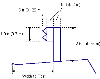
Guardrail Width |
Width of the guardrail widening link for fill slopes using Steep Fill Slope. Use zero for no guardrail widening. |
Numeric, positive |
0.6 m 2 ft |
|
Guardrail %Slope |
% slope of the guardrail widening link |
Numeric |
-2 (%) |
|
Include Guardrail Omit Guardrail |
Include to insert links for the guardrail structure on the guardrail widening segment. Omit does not insert the guardrail structure. |
Include / Omit |
Omit |
|
Width to Post |
When the guardrail is included, the width from the attachment point to the inside edge of the guardrail post. |
Numeric |
0.3 m 1 ft |
|
Rounding Option |
Specifies to round off the daylight link at the catch point |
String |
None |
|
Rounding By |
Specifies what parameter is used for rounding |
String |
Length |
|
Rounding Parameter |
Specifies value for length or radius |
Numeric, positive |
1.500 ft |
|
Rounding Tesselation |
Specifies number of intermittent points on rounding links (maximum 10 links) |
Numeric, positive |
6 |
|
Place Lined Material |
Specifies to place optional material lining along daylight links. You can choose All Links, Daylight Links, Fill Links Only, and None. |
String |
None |
|
Slope Limit 1 |
Specifies the slope limit until which the associated material lining is placed |
Slope |
1 : 1 |
|
Material 1 Thickness |
Specifies the thickness of lined material. This thickness is measured perpendicular to the link. |
Numeric, positive |
12 inches |
|
Material 1 Name |
Specifies the name of the material applies for lining along grading links |
String |
Rip Rap |
|
Slope Limit 2 |
Specifies the slope limit until which the associated material lining is placed |
Slope |
2 : 1 |
|
Material 2 Thickness |
Specifies the thickness of lined material. This thickness is measured perpendicular to the link. |
Numeric, positive |
6 inches |
|
Material 2 Name |
Specifies the name of the material applies for lining along grading links |
String |
Rip Rap |
|
Slope Limit 3 |
Specifies the slope limit until which the associated material lining is placed |
Slope |
4 : 1 |
|
Material 3 Thickness |
Specifies the thickness of lined material. This thickness is measured perpendicular to the link. |
Numeric, positive |
4 inches |
|
Material 3 Name |
Specifies the name of the material applies for lining along grading links |
String |
Seeded Grass |
Target Parameters
This section lists the parameters in this subassembly that can be mapped to one or more target objects. For more information, see To Specify Corridor Targets.
|
Parameter |
Description |
Status |
|---|---|---|
|
Daylight Surface |
Name of the daylighting surface. The following object types can be used as targets for specifying the surface: surfaces. |
Required |
Output Parameters
|
Parameter |
Description |
Type |
|---|---|---|
|
Daylight Offset |
Offset of the daylight point |
Numeric |
|
Daylight Elevation |
Elevation of the daylight point |
Numeric |
Behavior
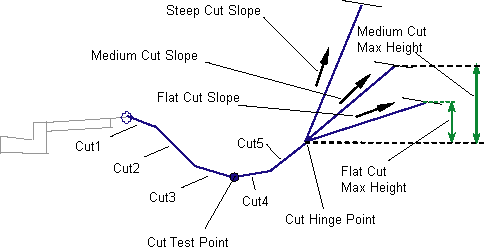
This subassembly is designed to accommodate a wide variety of clear zone, cut section, and fill section configurations. It allows up to eight links to be used in cut sections from the edge-of-roadway to the cut intercept hinge point, and any one of these links can be used as the cut test point. Up to three fill links can be used out to the fill hinge point, and provides special guardrail shoulder widening for steep fill conditions.
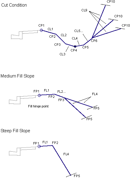
Cut links are denoted as Cut 1, Cut 2, up to Cut 8. The Cut Test Point input value indicates which cut link ends at the cut test point. The logical steps used are as follows:
- The cut surface links are constructed temporarily from Cut 1 to the cut link ending at the test point.
- If the test point, or any portion of the temporary surface, is below the target surface, the section is completed as a cut section. If the entire set of temporary links is above the target surface the section is completed as a fill section.
The cut example in the subassembly diagram show where five Cut links are defined. The cut test point is on the third link. The fill example shows two defined Fill links.
Like other daylight subassemblies, this subassembly optionally lets you add a lined material. You can specify three ranges of slopes. Material type 1 is applied if the slope of the links is up to the specified slope value. From slope 1 to slope 2, the second type of material applied. Similarly, if the slopes of links fall within slope 2 and slope 3 values, then material 3 is applied. If the link slopes are flatter than slope limit 3, then no material is applied.
If a lined material is added to the subassembly, then parallel links are added to the daylight links with specified thickness. This thickness parameter (for example, Material 1 Thickness) is measured perpendicular to the link. Bottom level links are coded with Datum and daylight links are coded with Top. Shapes enclosed by these materials are coded with material name.
In Civil 3D 2010 and previous versions, the Material Thickness parameter was measured vertically. In Civil 3D 2011 and later, this parameter is measured perpendicular to the link. Therefore, if you open a drawing containing these subassemblies that was created in Civil 3D 2010 or prior in Civil 3D 2011 or later, and then rebuild the corridor(s), this parameter will be changed to reflect the new behavior. Any volume reports that use this subassembly will be updated to reflect the new behavior.
Cut Section
- If the cut test point is above the target surface, the links are traced backwards from the test point until an intersection with the target surface is found. The section is terminated at this point.
- If the test point is below the target surface, the remaining cut links are added one by one. Each one is tested to see if it intersects the daylight surface. If so, the cut section terminates at the intersection point and the appropriate Hinge and Daylight codes are assigned.
- To close to the target surface in cut:
- If Include Daylight Link is set to False, no cut daylight intercept is calculated.
- The intercept to the daylight surface is calculated using the Flat Cut Slope value.
- If the height of the flat cut slope exceeds the Flat Cut Max Height, the intercept to the daylight surface is re-calculated using the Medium Cut Slope value.
- If the height of the medium cut slope exceeds the Medium Cut Max Height, the intercept to the daylight surface is re-calculated using the Steep Cut Slope value.
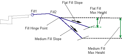
Fill Section
- Fill links are inserted outward from the attachment point to the fill hinge point, which is the outer edge of the last non-zero fill link.
- When a fill link intersects the daylight surface before reaching the hinge point, the section is terminated at the intersection and the appropriate Hinge and Daylight point codes are assigned.
- To close to the target surface in fill:
- The intercept to the target surface is calculated using the Flat Fill Slope value. If the height of the intercept link does not exceed the Flat Fill Max Height, this slope is used to add the link to the assembly, otherwise:
- The intercept to the target surface is re-calculated using the Medium Fill Slope value. If the height of the intercept link does not exceed the Medium Fill Max Height, this slope is used to add the link to the assembly, otherwise:
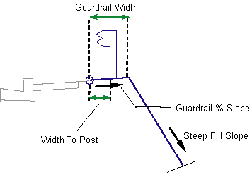
- If a non-zero guardrail width is given, the links (Fill 1, Fill 2 etc.) are removed. The guardrail widening link is added at the attachment point using the Guardrail Width and Guardrail %Slope parameters. The intercept to the target surface is re-calculated from the outside edge of the guardrail widening link using the Steep Fill Slope value, and the link is added to the assembly.
- If the guardrail width is zero, the steep fill slope is applied from the fill hinge point.
A guardrail structure may be applied to fill sections that meet the criteria for using the steep fill slope. If this criteria is met, the Guardrail Width is not zero, and Include Guardrail is set to true, then a guardrail structure is drawn at the station. The dimensions of the guardrail structure are fixed as shown in the diagram below.
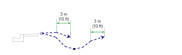
Layout Mode Operation
In layout mode, this subassembly shows both the cut and fill condition flat-slope solutions in dashed lines. The daylight link is extended outward for a horizontal distance of 3 meters or 10 feet, and terminates with an arrowhead.
Point, Link, and Shape Codes
The following table lists the point, link, and shape codes for this subassembly that have codes assigned to them. Point, link, or shape codes for this subassembly that do not have codes assigned are not included in this table.
|
Point, Link, or Shape |
Code |
Description |
|---|---|---|
|
CP(n+1) |
Ditch_Out |
Ditch test point at the end of Cut Link n, where n is the cut test point link number |
|
CP (1 to n) |
Hinge Hinge_Cut |
Hinge point for the cut intercept slope |
|
CP10 |
Daylight Daylight_Cut |
Cut slope stake point |
|
FP (1 to n) |
Hinge Hinge_Fill |
Hinge point for the fill intercept slope |
|
FP5 |
Daylight Daylight_Fill |
Fill slope stake point |
|
All links |
Top Datum |
All cut, fill, and guardrail links |
|
Guardrail points |
None |
No codes are assigned to the points on the guardrail structure, if included. |
|
Guardrail links |
Guardrail |
All links comprising the guardrail structure, if included. |
|
Final daylight link |
Top Datum Daylight Daylight_Cut |
Daylight link for cut section |
|
Final daylight link |
Top Datum Daylight Daylight_Fill |
Daylight link for fill section |
Coding Diagram