
You can specify the type of connection points to use when laying out pipe networks.
Connection points on a structure define the locations to which pipes can be connected.
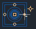
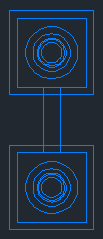
The following illustration shows a rectangular structure which has connection points at the center of each wall (indicated with circles), and an insertion point at the center of the structure.
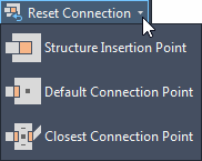
When you are laying out a pipe network, you can select which type of connection point to use. You can also reset the connection points after laying out the pipe network.
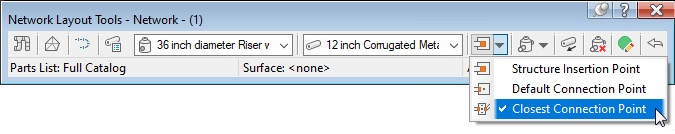
 Structure Insertion Point: This option places the structure based on its insertion point and the structure insertion point is used as the connection point. This option replicates the existing behavior in
Autodesk Civil 3D 2019 and earlier.
Note: When this is the only option available for selection in the list and the other options are grayed out, it means that the structure you selected to insert does not have connection points defined on it.
Structure Insertion Point: This option places the structure based on its insertion point and the structure insertion point is used as the connection point. This option replicates the existing behavior in
Autodesk Civil 3D 2019 and earlier.
Note: When this is the only option available for selection in the list and the other options are grayed out, it means that the structure you selected to insert does not have connection points defined on it. Default Connection Point: This option places the structure based on the default connection point (the first connection point that is defined for a structure) and the default connection point is used as the connection point.
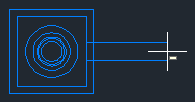
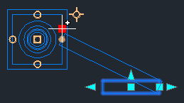
 Closest Connection Point: This option places the structure based on its insertion point and the closest connection point is used as the connection point. After you insert a structure, when you move your cursor over the structure, you can see the available connection points, shown as circles in the following illustration.
When you move the cursor away from the structure, a temporary graphic representing the pipe is drawn from the connection point on the structure that is closest to the cursor.
As you move your cursor around the structure, the pipe graphic is drawn from the next closest connection point.
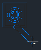
When you select the point for the second structure, the structure is placed in the drawing and the end of the pipe is connected to the connection point on the second structure that is closest to the first structure.
Pipe Network Editing
When you grip edit a pipe network, the end points of the pipes can connect to a connection point or to the insertion point on the structure. The following illustration shows a pipe connecting to the connection point that is closest to the cursor location when grip editing the pipe.
You can also use the Reset Connection commands on the Pipe Network contextual ribbon tab to reset pipe connections.
Pipe Network Content with Connection Points and Grips
The following part types in the Generic Drainage with Pipe Connections - Imperial and Generic Drainage with Pipe Connections - Metric catalogs have been updated to have new connection points and grips:
- Rectangular Underground Structures: Pipe connection points have been added at the inside center of each wall.
- Eccentric Cylindrical Structures: A single pipe connection point has been added to the center of the underground barrel.
- Rectangular Grates: Move grips have been added to the back left corner, back center, and back right corner of each rectangular grate. Rotation grips have been added to the back center of each rectangular grate.
You can add connection points to custom parts by using the Infrastructure Parts Shape Utilities tools in Autodesk Inventor. For more information, see To add reference points.