
Add reference points to drainage surface structure parts in Autodesk Inventor in order to define the movement and rotation grips that can be used with your parts in Autodesk Autodesk Civil 3D
Reference points are named work points that you add to your surface structure models in Autodesk Inventor to determine where rotation and movement grips will appear on the parts after being brought into Autodesk Civil 3D. There are three types of reference points that you can assign to a drainage surface structure:
- A reference point that defines where a movement grip will be placed.
- A reference point that defines where a rotation grip will be placed.
- A reference point that defines where both a movement and rotation grip will be placed.
Note: It is not recommended to add reference points to Underground Structures and Grates, Covers, or Frames.
- In Autodesk Inventor, click
Environments tab
 Infrastructure Part Shape Utilities
Reference Point
The Add Reference Point dialog is displayed. By default, the Reference Point Description will begin with "P1" unless you specify a different reference point number.
Infrastructure Part Shape Utilities
Reference Point
The Add Reference Point dialog is displayed. By default, the Reference Point Description will begin with "P1" unless you specify a different reference point number.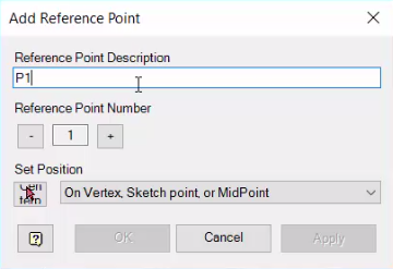
- Input a description in the Add Reference Point dialog. The description that you input for each reference point will determine how each reference point is recognized by Autodesk Civil 3D.
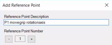
- For a reference point that defines both a movement grip and a rotation grip, input "movegrip rotationaxis" after the reference point number. For example, "P1 movegrip rotationaxis".
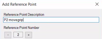
- For a reference point that defines a movement grip, input "movegrip" after the reference point number. For example, "P2 movegrip".
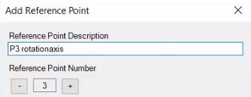
- For a reference point that defines a rotation grip, input "rotationaxis" after the reference point number. For example, "P3 rotationaxis".
- For a reference point that defines both a movement grip and a rotation grip, input "movegrip rotationaxis" after the reference point number. For example, "P1 movegrip rotationaxis".
- Click Set Position
 .
Note: There is no need to change the default set position option. "On Vertex, Sketch Point, or MidPoint" is the recommended option.
.
Note: There is no need to change the default set position option. "On Vertex, Sketch Point, or MidPoint" is the recommended option. - Hover your cursor over a Vertex, Sketch Point, or MidPoint.
Available points will display a yellow circle.
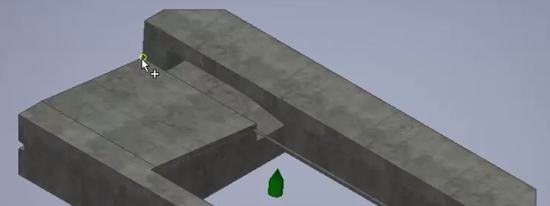
- Click to place the reference point.
The reference point you just placed will display as an orange circle.
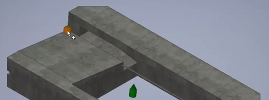
- Click OK in the Add Reference Point dialog.
Note: When you open your part shape templates in the Infrastructure Parts Editor, you can visually validate your part families and assemblies. Reference points will be highlighted in the Sizes View and Assembly View panes. See To add or modify an assembly for more information.
- After you publish your catalog from the Parts Editor and open your parts in Autodesk Civil 3D, the different reference points you added will be displayed with different grip icons:
- Reference points for movement display as diamonds
 .
.
- Reference points for rotation display as circles
 .
.
- Reference points for movement display as diamonds