
Use this dialog box to view and change section view-related settings.
This topic documents settings in all section view-related Edit Settings dialog boxes (drawing-level, feature-level, and command-level).
- Drawing-level ambient settings are identified by the
 drawing icon.
- Section view feature settings are listed near the top of this dialog box, after the General property group, and are identified by the
 section view icon.
- Section view command settings are identified by the
 command icon.
For general information about drawing, feature, and command settings and their interaction, see About Autodesk Civil 3D Settings.
For information about drawing-level ambient settings, see Ambient Settings Tab (Drawing Settings Dialog Box).
Default Styles
Use these settings to specify the default styles assigned to section view components:
- Marker Style
-
Specifies the default marker style for section view points for offset elevation and depth grade labels. Click in the Value column, and click
 to select a style in the
Marker Style dialog box.
to select a style in the
Marker Style dialog box.
- Section View Offset Elevation Label Style
-
Specifies the default section view offset elevation label style. Click in the Value column, and click
to select a style in the
Section View Offset Elevation Label Style dialog box.
- Section View Depth Grade Label Style
-
Specifies the default section view grade label style. Click in the Value column, and click
to select a style in the
Section View Depth Grade Label Style dialog box.
- Section View Style
-
Specifies the default section view style. Click in the Value column, and click
to select a style in the
Section View Style dialog box.
- Section View Band Set
-
Specifies the default section view band set style. Click in the Value column, and click
to select a band set in the
Section View Band Set dialog box.
- Section Label Set
-
Specifies the default section label set style. Click in the Value column, and click
to select a label set in the
Section Label Set dialog box.
- Group Plot Style
-
Specifies the default group plot style for the multiple section view objects. Click in the Value column, and click
to select a style in the
Group Plot Style dialog box.
- Section Projection Label Style
-
Specifies the default style for labels on projected objects. Click in the Value column, and click
to select a style in the
Section Projection Label Style dialog box.
- Section Crossing Label Style
-
Specifies the default style for labels on crossings. Click in the Value column, and click
to select a style in the
Section Crossing Label Style dialog box.
Default Name Format
Use these settings to specify the template for naming the section view and the layouts created with the Create Section Sheets command.
- Section View Name Template
-
Specifies the default section view name template.
The default format is <[Section View Station (Uft|FS|P2|RN|Sn|OF|AP|B2|TP|EN|W0|DZY)]> (<[Next Counter(CP)]>).
The Section View Station name is followed by a number of parameters that define how the text is displayed:
- U—Units: Select one of ft (foot), m (meter), mile (mile), km (kilometer), in (inch), or yd (yard). The default is Uft.
- F—Format: Select either S (station format) or D (DD.DDDDDD decimal). The default is FS.
- P—Precision: Select one of 0 (1), 1 (0.1), 2 (0.01), ... , or 8 (0.00000001). The default is P2.
- R—Rounding: Select one of N (round normal), U (round up), or T (truncate). The default is RN.
- S—Sign: Select one of n (sign negative ‘-’), Bn ((Bracket negative)), a (sign always (±)), D (drop sign), BL (‘(‘ left prentice), or BR (right prentice ‘(‘). The default is Sn.
- O—Output: Select one of F (full), LD (left of decimal), RD (right of decimal), DS (decimal character), LB (left of station character), RB (right of station character), BBD (between station character and decimal), or BC (station character). The default is OF.
- A—Decimal character: Select either P (‘.’ period) or C (‘,’ comma). The default is AP.
- B—Station character position: Select one of 1 (1+0), 2 (1+00), 3 (1+000), 4 (1+0000), or 5 (1+00000). The default is B2.
- T—Station character: Select one of P (plus sign ‘+’), M (minus sign ‘-’), A (automatic (±)), U (underscore ‘_’), or N (none). The default is TP.
- E—Drop decimal for whole number: Select either N (No) or Y (Yes). The default is EN.
- W—Minimum display width: Select one of 0 (none), 1, 2, ..., 32. The default is W0.
- DZ—Drop leading zeros: Select one of Y (yes) or N (no). The default is DZN.
For example, a section view name, using the above defaults and following the “rules” of the parameters, could look like this:
2+50.00 (2)
Click in the Value column, and click
to make changes in the
Name Template dialog box.
- Cross Section Sheet Layout Name Template
-
Specifies the default name template that is used to name layouts that are created with the Create Section Sheets command.
Section View Creation
Use these settings to establish the defaults assigned for section view creation:
- Specify Section View Offset Range
-
Specifies whether an offset range is set for the creation of a section view.
- Specify Section View Height
-
Specifies whether the default section view height is set for the creation of a section view.
- Section Group Elevation Range
-
Specifies how the elevation range of the section group is set:
- Lowest Elevation
- Mean Elevation
- Follow a Section
- Corridor Point Code Labeling Method
- Specifies how corridor point code labeling is controlled.
Note: Changing this setting does not change the labeling method for section views that are already in the drawing.
- Section Label Set: Specifies that corridor point code labels are controlled by the label set. Using this option, you can configure the corridor point code labels so they do not overlap.
- Section Code Set Style: Specifies that corridor point code labels are controlled by the code set style.
- Add Labels to Points Interpolated from DREF Corridors
- Displays labels on points that are interpolated from data referenced corridors.
When this setting is set to On, points that are interpolated from data referenced corridors are labeled and symbols are displayed on the points.
When you move the cursor over these symbols, tooltips are displayed to inform you to confirm the actual value of the label in the source drawing.
For a data referenced corridor, the following rules determine whether the corridor points for a particular section are considered to be interpolated:
Sample Line Interpolated A straight sample line on the data referenced corridor in the host drawing is at the same station as a corridor assembly station in the source drawing. No Note: Labels for these points are not affected by the Add Labels to Points Interpolated from DREF Corridors setting.A straight sample line on the data referenced corridor in the host drawing does not match a corresponding corridor assembly station in the source drawing. Yes Note: Labels for these interpolated points can be displayed by changing the Add Labels to Points Interpolated from DREF Corridors setting to On.A skewed sample line on the data referenced corridor in the host drawing is at the same station as a corridor assembly station in the source drawing. No Note: Labels for these points are not affected by the Add Labels to Points Interpolated from DREF Corridors setting.Note: To display the correct (not interpolated) label values for a data referenced corridor, you can apply the corridor assembly to all the stations in the data shortcut source drawing that you want to label. The assembly should be applied at the same stations as the sample lines that are created on the data referenced corridor. After the assembly is applied to the stations in the source drawing and the data shortcut references are synchronized, the labels on the data referenced corridors will be updated with the correct values.For more information about labeling corridor points, see To Label Corridor Point Codes in Section View.
Default Projection Label Placement
Use these settings to specify the default placement of labels for objects projected to section views:
- Dimension Anchor Option
-
Specifies whether the default anchor option will be Fixed, Above, Below, Graph View Top, or Graph View Bottom.
- Dimension Anchor Elevation Value For Projections
-
Specifies the default value for anchor elevation. Enter a value or click
 and select an elevation in the drawing area.
- Dimension Anchor Plot Height Value For Projections
-
Specifies the default value for anchor plot height (in paper space units). Enter a value or retain the existing default value.
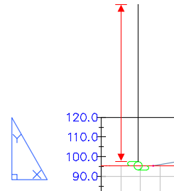
The Dimension Anchor Plot Height Value for Projections option controls the leader line height when the Dimension option is used for either the start or end anchor point in the projection or crossing label style.
Crossing Options
- Crossing Tolerance
-
Specifies the distance within which an object must be from a sample line to be displayed as a crossing.
Note: The crossing tolerance does not apply to 3D solids, 3D polylines, feature lines, or survey figures, which are considered to be crossing only if they intersect a sample line.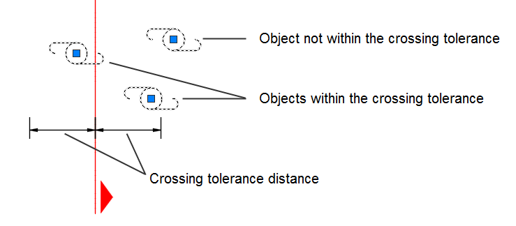
For example, if this value is set to 1 foot, an object's centroid grip can be within one foot of the sample line and still be displayed as a crossing in a section view.
If this value is set to zero, the object's centroid grip must be exactly on the sample line in order to be displayed as a crossing in a section view.
The maximum value that you can specify for this setting is 15 feet or 5 meters.
Table Creation
Use these settings to specify defaults for creating tables with section views.
- Split Table
-
Specifies whether a table is split into two or more sections after a specified maximum number of rows has been met.
- Maximum Rows Per Table
-
Specifies the maximum number of rows to include per section. If the number of data rows exceeds the specified maximum, the table is split into sections, and they are displayed either side by side (left to right), or stacked vertically.
- Maximum Tables Per Stack
-
Specifies the maximum number of sections to include in each stack.
- Table Spacing
-
Specifies the spacing between tables.
- Total Volume Table Style
-
Specifies the style for a total volume table. Click in the Value column, and click
to select a style in the
Total Volume Table Style dialog box.
- Material Volume Table Style
-
Specifies the styles for a material volume table. Click in the Value column, and click
to select a style in the
Material Volume Table Style dialog box.
- X Offset
-
Specifies the horizontal offset of the table.
- Y Offset
-
Specifies the vertical offset of the table.
- Tile Direction
-
Specifies the direction in which the table tiles (across or down).
- Section View Anchor
-
Specifies the section view anchor (Top/Middle/Bottom, Left/Center/Right).
- Table Anchor
-
Specifies the location of the table anchor (Top/Middle/Bottom, Left/Center/Right).
- Table Layout
-
Specifies whether the layout of the tables will be horizontal or vertical, in relation to the section view.
Multiple Section View Creation
Use these settings to specify defaults for creating multiple section views.
- Specify Multiple Section View Station Range
-
Specifies whether a station range is set for the creation of multiple section views.
- Default Section View Height
-
Specifies the default height for section views. Enter a height in the Value column or click
and select a height in the drawing area.
- Placement Option
-
Specifies the default placement option for the section views.
- Production : Use this option if you intend to use the Create Section Sheets command to generate paper space layouts that contain section views.
- Draft : Use this option if you intend to create an array of section views in model space for draft purposes.
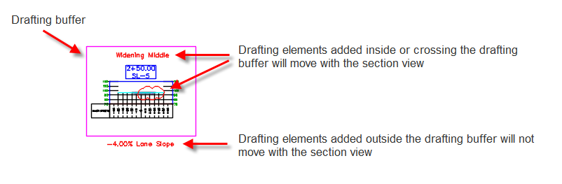
Drafting Buffer
Drafting elements that are added within or crossing section view drafting buffers are bound with the section views, and are moved with the section views if they are moved.
For more information, see About Section View Drafting Buffers.
Use the following settings to specify defaults for the drafting buffer margins when creating section views.
- Above Grid/Below Grid
-
Specifies the amount of space for the drafting buffer above and below the section view grid.
- Left of Grid/Right of Grid
-
Specifies the amount of space for the drafting buffer to the right and the left of the section view grid.
Sheet Creation
- Sheet Set Use
-
Specifies whether you create a new sheet set for any new sheets, or whether you add to an existing sheet set.
Object Selection Options
- Projection Rule Type
-
Specifies the default projection rule when the Project Objects To Multiple Section Views dialog box is displayed.
- By Percentage: Select this option to specify a percentage of distance before and after the sample line.
- By Distance: Select this option to enter absolute distances before and after the sample line.
- Percentage Before Current Sample Line
-
Specifies the default distance percentage before the sample line.
- Percentage After Current Sample Line
-
Specifies the default distance percentage after the sample line.
- Distance Before Current Sample Line
-
Specifies the default distance before the sample line.
- Distance After Current Sample Line
-
Specifies the default distance after the sample line.