There are several ways fittings can be inserted while laying out a pressure network. You can select a specific fitting, such as a tee or cross, from the Fittings list and add it to the drawing. Fittings are organized by material. In plan view, fittings can be added to the ends of a pipe or inserted anywhere along a pipe. Layout cues are displayed to indicate where the fitting can be inserted.
To Add Reducers and Elbow Fittings
- Create a pipe run and begin laying it out using the
Pressure Network Creation Tools or the
Create New Pipe Run command.
Note: Bends can be automatically added between pipe segments when laying out the pressure network with the Add Bends Automatically option selected on the Pipe Run panel.
- On the Pressure Network Plan Layout ribbon tab, on the Layout panel, select the type of reducer or elbow to add.
- Click
Add Fitting
 .
.
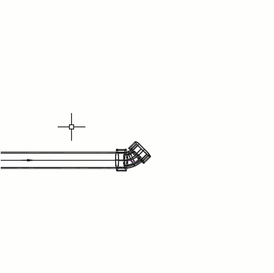
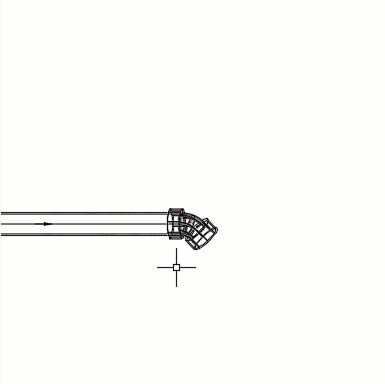
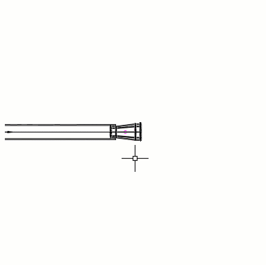
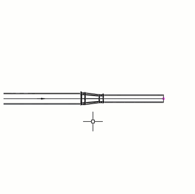
- Place your cursor at the desired insertion point. Click to place according to the connection glyphs:
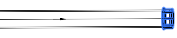
 at the ends of a pipe run.
 along a pipe run. Elbows can be inserted at points of intersection (PI) in a pipe run.
- The fitting is placed in the pipe run.
| Reducer and Elbow Adjustments | Adjustment Example |
|---|---|
|
Select the pipe run and click
|
|
|
Select the elbow and click
|
|
|
Select the pipe run and click
If the pipe size is available from the drawing part list, the pipe will resize to match the fitting port. |
|
|
Select the reducer and click
|
|
|
Select a reducer and click
|
|
 (Continue Layout) to continue the run from an elbow.
 (Flip) to flip its orientation.
 (Flip) to flip its orientation.
 (Slide) to move the reducer along the pipe run.
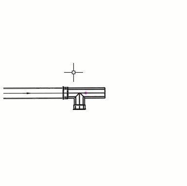
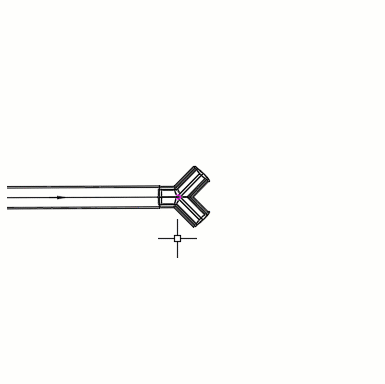
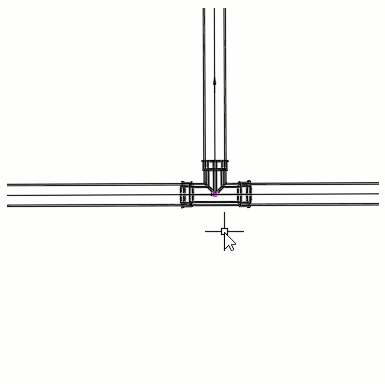
To Add Fittings for Branches or Intersections
- Create a pipe run and begin laying it out using the Pressure Network Creation Tools or the Create New Pipe Run command.
-
Note: You can add branch fittings at the intersection of existing pipe runs using the Add Branch Fitting command.
- On the Pressure Network Plan Layout ribbon tab, on the Layout panel, select the wye, tee, or cross fitting to add.
- Click
Add Fitting
.
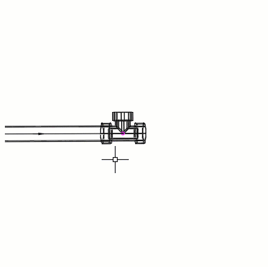
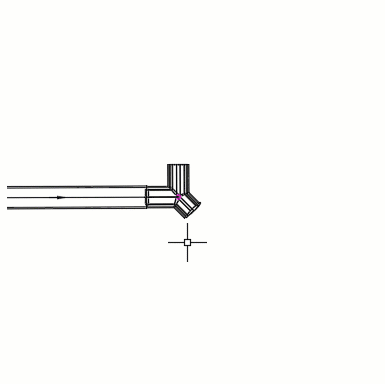
- Place your cursor at the desired insertion point. Click to place according to the connection glyphs:
- at the ends of a pipe run.
- along a pipe run.
- The fitting is placed in the pipe run.
| Branch Fitting Adjustments | Adjustment Example |
|---|---|
|
To continue a pipe run through a fittings (such as tees and crosses), select the pipe run and click
If the pipe size is available from the drawing part list, the pipe will resize to match the fitting port. |
|
|
To add new pipe-runs from fittings (such as tees, wyes, and crosses), select the fitting and click
If the pipe size is available from the drawing part list, the pipe will resize to match the fitting port. |
|
|
Select a fitting and click
|
|
|
Select the fitting and click
|
|
|
Select a fitting that has a pipe run through it (such as tees, crosses, and lateral wyes) and click
|
|
To Add Caps to a Pipe Run End
- Create a pipe run and begin laying it out using the Pressure Network Creation Tools or the Create New Pipe Run command.
- On the Pressure Network Plan Layout ribbon tab, on the Layout panel, select the type of cap to add.
- Click
Add Fitting
.
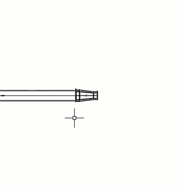
- Place your cursor at the desired insertion point. Click to place according to the connection glyph
at the end of a pipe run.
- The fitting is placed in the pipe run.