
You can use Autodesk Civil 3D corridor modeling to create flexible and configurable 3D models of corridors, such as roads, highways, and railways.
A corridor model builds on and uses various Autodesk Civil 3D objects and data, including subassemblies, assemblies, surfaces, feature lines, alignments, and profiles. The corridor manages the data, tying various assemblies (applied for different ranges of stations) to the baselines and their finished grade profiles.
Corridors persist in a drawing as objects with the name AeccCorridor. Corridor objects include corridor body geometry, longitudinal feature lines, embedded surfaces, rendering support, and slope hatching support.
A corridor can define and display components, such as:
- Feature lines connecting points along the point codes, which are defined in the subassemblies (used to create the assemblies).
- Surfaces, using link codes and feature lines.
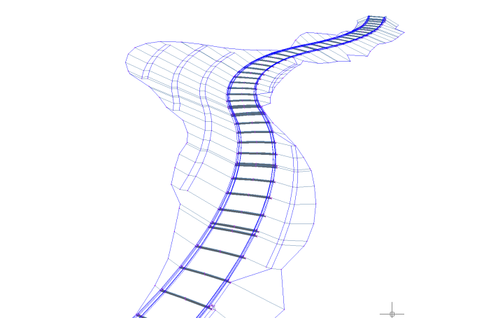
A corridor object is created from a baseline (alignment or feature line) by placing 2D sections (assemblies) at incremental locations, and by creating matching slopes that reach a surface model at each incremental location.
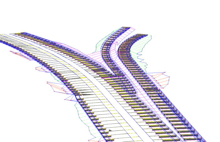
You can create corridors with multiple baselines, which enables you to create more complex designs, such as intersections.
Corridors are created from and based on existing Autodesk Civil 3D objects, which include:
- Horizontal Baselines (alignments or feature lines). Used by a corridor as its centerline.
- Vertical Baselines (profiles or feature lines). Used to define surface elevations along the horizontal baseline.
- Surfaces. Used to establish elevations along baselines (by way of profiles or feature lines) and as corridor targets. .
- Subassemblies. A fundamental component of a corridor model. Subassemblies define the geometry of a corridor section (assembly). For example, a typical roadway may be composed of paved lanes (on either side of the centerline), a paved shoulder, a gutter and curb, and a roadside grading. These parts are defined independently as subassemblies. You can stack any type of subassembly to make up a typical assembly and apply the same assembly for a station range along a horizontal baseline.
- Assemblies. Represent a typical section of a corridor. Assemblies comprise one or more subassemblies connected together.
After you have created a corridor, you can extract data from it, including surfaces, feature lines (as polylines, alignments, profiles, and grading feature lines), and volume (quantity takeoff) data.
Corridors have their own display style and also inherit styles from their components.
Managing and Editing Corridors
A corridor is defined by at least one baseline and an assembly that is applied for a range of stations on that baseline. In many cases, corridors will have different assemblies at different stations, depending on the existing ground and other design considerations. Also, it may be necessary to build a corridor model that is controlled by multiple baselines, for example, one that includes intersection objects. To add and edit this type of complexity, you can use the Parameters tab of the Corridor Properties dialog box, where you can modify the associated baselines and assemblies, change assembly frequency and range, and update targets.
You can use the Corridor Properties dialog box to view and or change:
- a corridor’s administrative information, such as name description, and object style
- parameters such as baselines, frequencies, and targets
- code sets
- corridor feature lines, surfaces, boundaries, and slope patterns
Many corridor editing commands can also be accessed on the Corridor ribbon tab.
To display the Corridor tab in the ribbon, do one of the following:
- In the drawing window, click a corridor to select it.
- In the ribbon, click the Modify tab
 Design panel Corridor.
- In Toolspace, on the Prospector tab, right-click a corridor and then click Select.