
The first step in creating the MD file is to set up the machine hierarchy, which is done using the Parent/Child Relationships dialog. You must add all components that you want to show during machine simulation as children of machine in the Part View. The main purpose of this is to create a hierarchy of movement, but static components (such as body, base, or even logos) are also included. There may be solids that you choose to leave in the document even though they are not displayed during simulation (for example the doors, which should always be hidden during simulation, or a parts-catcher mechanism for which you plan to add the simulation at a later time).
Here are examples of two different machines with their parent/child relationships structures set up.
|
Turn/mill example:
|
5-axis milling example:
|
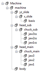
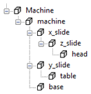
In the turn/mill example, the jaws are children of the chucks, which are children of the heads. In the mill example, head sits on the z_slide, which sits on the x_slide.
Additional notes
- It is not possible to have a child solid linked to several parent solids. Therefore, if you require this, you must make a copy of the child solid.
- If you ever need to remove these relationships to be rebuilt or replaced, it is best practice to remove the lowest objects in the hierarchy first. In the 5-axis milling example above, if you wanted to remove the objects x_slide, z_slide, and head, you would remove head first, then z_slide, then x_slide.
- The machine tree is easier to navigate if you make non-moving solids children of the main (non-moving) body. Because they do not move, this has no functional effect, but makes it easier to navigate and adjust the solids that move.