
- Right-click the stock in the Part View and select Properties.
- On the
Dimensions tab of the
Stock Properties dialog, select the stock shape and enter the dimensions:
- Block
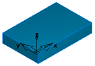
Enter the Length (X dimension), Width (Y dimension), and Thickness (Z dimension).
- Round
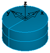
Select which axis points along the stock, and enter the Length and OD (outside diameter). For tube stock, enter a positive number as the ID (inside diameter).
- N-sided
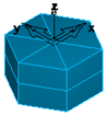
Select which axis points along the stock, and enter the OD (outside diameter), the number of Sides, and the Length of the stock.
- Block
- If you want to move the stock, enter the
X,
Y, and
Z coordinates of the new location or click
Pick Location
 and select a point in the graphics window.
- For Swiss Turn documents, in the
Swiss tab, specify the
Stock and
Guide Bushing options:
- Working Part Length — Enter the initial working length of the part that is exposed past the main chuck. This is often the finished part length, or a fraction of it if rechucks will be performed.
- Face Allowance — This value is passed to the post for initial chucking. Select Use Face Feature to find the face allowance from the Face feature. If there is no Face feature, deselect Use Face Feature and enter a Face Allowance.
- Sub Face Allowance — This value is passed to the post for initial chucking. Select Use Face Feature to find the face allowance from the Face feature on the sub-spindle. If there is no Face feature, deselect Use Face Feature and enter a Face Allowance.
- Use a parametric guide bushing — Select to enter the Length and Outer Diameter of the guide bushing used during machine simulation. Deselect to the use the pre-defined solid in the Machine Design file.
- Click Apply to preview the stock in the Graphics window.
- Click OK to close the dialog.