
You can bulk upload and configure the list of sensors you want to monitor in Info360 Plant using a CSV template.
For instructions on creating individual sensors, see Create a Sensor.
There are two types of sensor you can create:
- Physical Sensor: Physical sensors are for live sensor data retrieved via a system connection. Make sure you have installed the Info360 Plant data connector first.
- Virtual Sensor: Virtual sensors are for time series data generated within Info360 Plant (e.g., in Forms).
To create sensors in bulk
- Prepare your bulk sensor creation CSV file. Download and unzip the template CSV file:
sensors-rfi-template.
See Prepare the Sensor_RFI_Template below for an explanation of each of the fields. There are also examples in the template (which should be deleted).
- Go to Admin
 Sensor configuration.
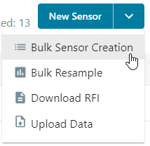
- Click on the drop-down arrow beside the New Sensor button in the right-hand corner and select Bulk Sensor Creation.
- Drag and drop your CSV file, then click Create Sensor.
Prepare the sensors_rfi_template
Supported characters in all fields except the Tag Value field are limited to: all alphanumerics, space, and _ . - :
- Sensor ID*: This will be used as the sensor's GUID in the application. For physical sensors, this is commonly set to a value similar to the "Tag Value" (see field further below) but is restricted to the supported characters listed above.
- Alias*: A user-friendly name that will be displayed throughout Info360 Plant when this sensor is referenced (for example, in charts or analytics). For example, "Elm_Street_Pump_Discharge_Pressure".
-
Sensor Type*: Only one of the following allowed types may be defined per sensor and the text must match exactly.
- Ammonia
- Billing
- Chlorine Residuals
- Color Unit
- Concentration
- Conductivity
- Currency
- Current
- Electric Potential
- Flow Rate
- Fluoride
- Free Ammonia
- HAA5
- Head
- Length
- Level
- Linear Charge Density
- Mass
- Monochloramine
- Nitrite
- Other
- Percent
- pH
- Power
- Pressure
- Radon Level
- Rain Gauge
- Setting
- Status
- Tank Level
- Temperature
- Threshold Odor Number
- Time Duration
- TOC
- Total Chlorine
- Total Hardness
- Total THMs
- Turbidity
- UV Dose
- UV Intensity
- UV254
- UVT
- Velocity
- Volume
- Unit: The unit of measurement for the sensor. This field will depend on the Sensor Type defined above. See the accepted units listed in Units of Measurement per Sensor Type.
- [Physical Sensors only]
Interval: The interval (in seconds) at which the sensor data should be sampled. If this field is left blank, the interval defined in the related System Connection (the "Data Source" defined) will be used. Data samples in excess of 1 per minute will be aggregated.
For ODBC and OLE DB, this interval determines how frequently streaming-related queries are issued against the SQL server and the time range requested in those queries.
For OPC UA, this is the sampling interval we request the OPC UA server to use. The publishing interval is set to push each sample immediately. A larger interval means less raw data.
Note: If the related System Connection has a larger interval, this will override the Sensor Interval defined here. - Latitude: In decimal degrees (e.g. 35.83932) and in the range -90,90. Negative indicates south of the equator.
- Longitude: In decimal degrees (e.g -104.58393) and in the range 180,-180. Negative indicates west of the prime meridian.
- [Physical Sensors only] Tag Value*: The unique identifier for the sensor/signal as specified in either the SCADA historian or OPC UA server.
- Fields specific to ODBC and OLE DB:
- Sensor Table*: The name of the table in the source data historian where the sensor data are stored. Currently, Info360 Plant only supports a table schema which contains at least each of following three data points: sensorID, datetime, and value
- Sensor Date Field*: The name of the column where the date information is stored.
- (Deprecated) Sensor Time Field: The name of the column where the time information is stored. This field is used if the date and time stamps are stored separately in the historian.
- Sensor Channel Field*: The name of the column where the reported sensor value is stored.
- Sensor ID Field*: The name of the column where the Tag Value is stored.
- [Physical Sensors only] Data Source Name: The name of an existing System Connection. If this is not defined, the system will attempt to use the first connection it finds during the ingest process. If there is none, it will remain undefined.
-
Data Source Type: For physical sensors, this should match the type of the linked System Connection. Supported values are ODBC, OLEDB, and OPC-UA. If undefined, it will be treated as ODBC.
For virtual sensors, this should be FORM.
- [Tank Level Sensors only]: To add the tank diameter and vertical offset for a cylindrical tank, fill in the following values. These will be used to calculate the volume.
- Tank Type: For cylindrical tanks, enter 'cylindrical' (all lower case). For non-cylindrical tanks, leave blank.
- Tank Diameter: Enter the tank diameter in the same unit of measurement used by the tank level sensor.
- Tank Offset: Enter the tank offset in the same unit of measurement used by the tank level sensor.
To set the level to reference the tank base, enter an offset of 0. To set it to reference mean sea level, enter the offset between the tank base and mean sea level.
See Sensors for more information on configuring sensors.
If your new sensors don't appear on the map after 5 minutes and after refreshing your browser, see Troubleshoot: Changes to Sensors Don't Appear on Map.