Add dimensions in orthographic drawing views
On the ribbon, click Annotate tab
 Dimension panel
  Dimension
  .
.In the graphics window, select the geometry and drag to display the dimension.
To add a linear dimension for a line or edge, click to select the geometry.
To add a linear dimension between two points, two curves, or a curve and a point, click to select each point or curve.
To add a linear symmetric or linear diametric dimension, select two parallel lines or edges, right-click, and then select Dimension Type
 Linear Symmetric or Linear Diametric.
To add a linear foreshortened dimension, select two lines, edges, or points. Then right-click and select Dimension Type
 Linear Foreshortened.
To add a radial or diametric dimension, click to select an arc or circle.
To add an angular dimension, select two lines.
To add a foreshortened angular or arc length dimension, select two lines, right-click, and then select Dimension Type
 Angular Foreshortened, or Arc Length Foreshortened.
To add a dimension that rotates perpendicular to a selected edge: 1) Select a linear edge or 2 points. 2) Right-click and select Dimension Type
 Rotated. 3) Select a line to establish parallel or perpendicular direction of the dimension.
To annotate an arc segment with an arc length, angular, or chord length dimension, click to select the arc. Then right-click, and then select Dimension Type
 Arc Length, Arc Length Foreshortened, Angular, Angular Foreshortened, or Chord Length.
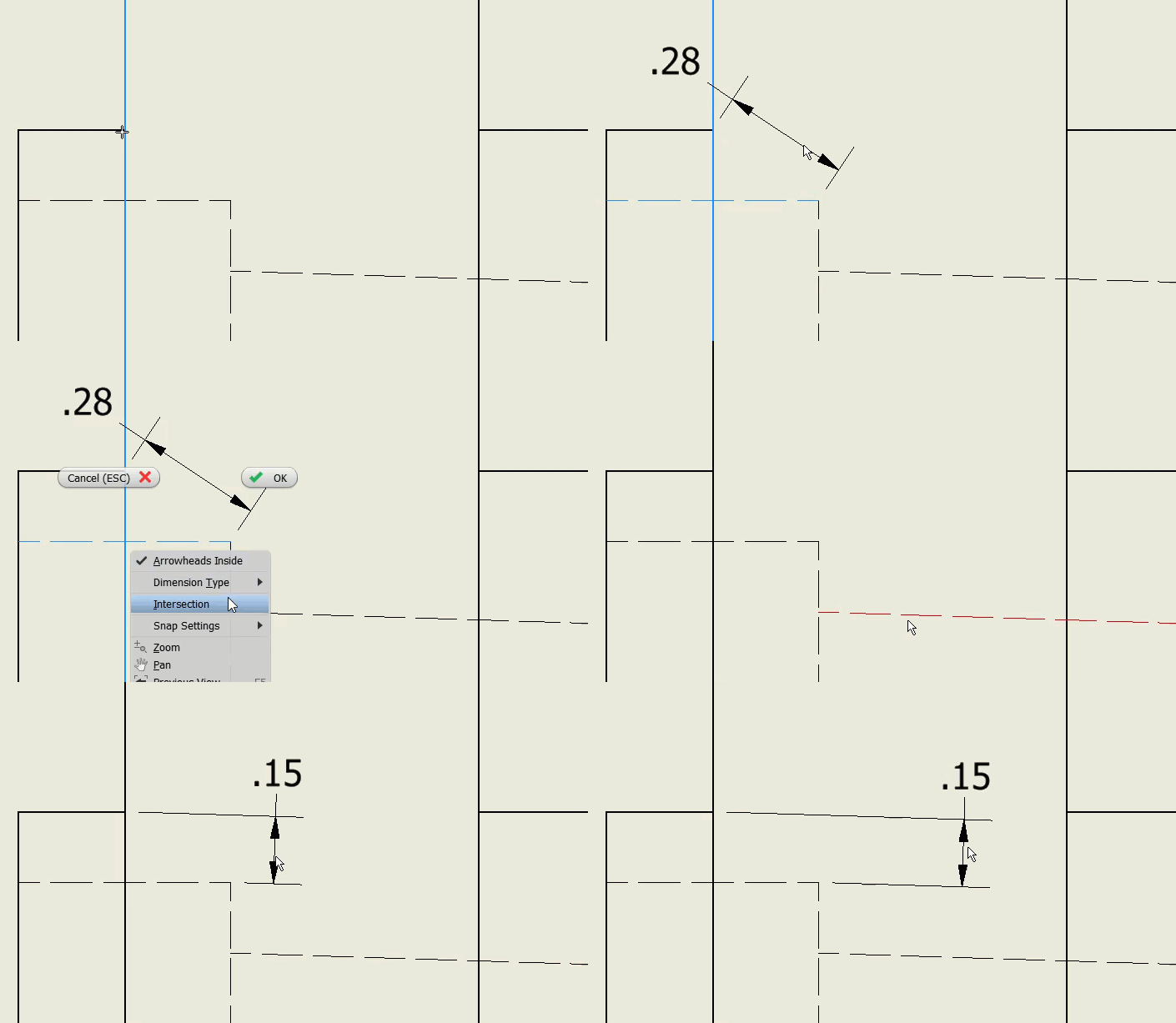
To add an implied intersection dimension, select the first curve, right-click, and then select the intersection. Select the second curve that defines the implied intersection, and then select the element (or other implied intersection) to dimension.
Tip: Selected objects in the drawing determine the type of dimension and commands available in the context menu. To change the settings or use different options, right-click, and click a command on the menu.
Click to place the dimension in the appropriate location.
Tip: When you create a leader line, hold the CTRL key on your keyboard to enable leader line snapping in 15° steps.
 Show Me how to create aligned dimensions
Create aligned dimensions based on each of the following inputs:
- A single line
- Two points
- Context menu selection
 Show Me how to create linear dimensions
Create linear dimensions based on the following inputs:
- A single line
- Two parallel lines
- Two points
- A line and an end point
- A line and a mid point
Create linear dimensions based on these inputs:
- A projected intersection and a line
- Two projected intersections
Create linear dimensions based on these inputs:
- Line and circle center point
- Line and circle quadrant point
- Line and circle nearest tangency
- Two circles between tangencies
- Two circles between center points
 Show me how to create angle dimensions
Create angle dimensions based on each of the following inputs:
- Two edges to create an acute angle dimension
- Two edges to create an obtuse angle dimension
- Three points
 Show Me how to create diameter dimensions
Create diameter dimensions using these context menu selections:
- Arrowheads Inside (On), Single Dimension Line (On), Leader from Center (Off) - Default
- Arrowheads Inside (On), Single Dimension Line (On), Leader from Center (On)
- Arrowhead Inside (On), Single Dimension Line (Off), Leader from Center (Off)
- Arrowhead Inside (Off), Single Dimension Line (Off), Leader from Center (Off)
 Show me how to create radius dimensions
Create radius dimensions using these context menu selections:
- Arrowheads inside (Off), Leader from center (Off), Jogged (Off) - default
- Arrowheads inside (On), Leader from center (Off), Jogged (Off)
- Arrowheads inside (On), Leader from center (On), Jogged (On)
