
About Tube and Pipe
What's New: 2024.2
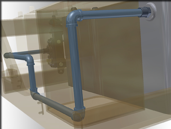
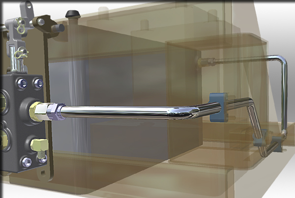
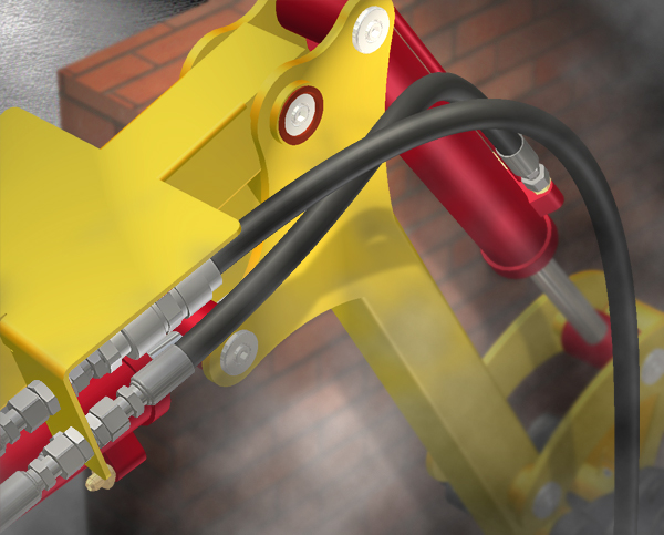
Autodesk Inventor Tube & Pipe is an add-in to the assembly environment. It adds design tools for routing rigid pipes, bent tubes, and flexible hoses to mechanical assemblies or product designs in the assembly environment.
You must have access to the tube and pipe library in Content Center before you use Tube & Pipe. Log in to the Vault Server or use Desktop Content, depending on how your installation is configured.
When you add tube, pipe, and hose routes in the context of an existing assembly, you create runs, set styles, define routes, and then populate them to complete the run. You can add and define multiple routes and runs. Optionally throughout the design process, you can add and remove specific conduit parts and fittings . Once a tube and pipe assembly is complete, the tube and pipe information can be represented in drawings and presentations.
Which tasks are performed with tube and pipe features?
When Autodesk Inventor Tube & Pipe is installed on your system, it adds the Create Pipe Run command to the Assemble tab so that you can create a primary runs assembly in a standard Inventor assembly.
When you add your first run, the run is activated in place and several additional Tube & Pipe-specific features are available.
In the top assembly environment, you can create view representations, positional representations, and model states in which appropriate tube and pipe edits are available. For instance, edit flexible hose routes in positional representations and suppress tube and pipe components in model states. In addition, you can transition a normal tube and pipe assembly to an iAssembly factory and create a tube and pipe interchangeability set of adaptive primary runs assembly members.
In the run environment, the Pipe Run tab is activated. Use the features added by the run environment to:
- Create and modify styles that conform to industry standards.
- Add one or more routes to the run.
- Place fittings from the active project work space into routes and runs.
- Connect two components relative to one another in the tube and pipe assembly.
- Populate all routes or selected routes.
- Place library fittings and conduit parts from the Content Center using AutoDrop on to routes and runs.
- Refresh library components to ensure they are up to date in the Content Center.
- Use the Parameters command to maintain model parameters and user parameters so as to assist in route design.
- Output run data in ISOGEN or Bending Machine format.
- Use the Model browser to visualize the tube and pipe assembly structure, edit runs, and to change visibility for routes, runs, and components.
In the route environment, the Route tab is activated. In addition to the style and browser features listed for runs, you can:
Design bent tube routes, rigid pipe routes, or flexible hose routes using auto route commands and sketched route commands.
Create derived routes and edit the underlying base sketches.
Add additional route points as you create or edit a route.
Place geometric constraints on route elements, and optionally include external geometry as reference geometry.
Add linear, angular, and radial dimensions to constrain route elements, and optionally switch route elements between driven dimensions and driving dimensions.
Note: You can copy driven dimensions and paste them as driving dimensions.Convert auto route regions to a series of continuous sketched route segments.
Move route points and segments in the auto route region dynamically.
Adjust flexible hose length dynamically or by entering precise distances.
Use the Parameters command to maintain model parameters and user parameters so as to assist in route design.
In the part environment, the Tube & Pipe Authoring command is added. You can author normal parts and custom iParts for future publishing to the Content Center.
Can tube, pipe, and hose routes be run in other add-in application assemblies?
Pipe runs can be placed in any other Autodesk Inventor add-in application assembly. Use Tube & Pipe as you would with any other native Autodesk Inventor assembly.
What can standard Autodesk Inventor installations do with tube and pipe data?
If Autodesk Inventor Tube & Pipe is not installed on the system viewing the tube and pipe data, interaction with the data is restricted. The main primary runs assembly and all that it contains is read-only.
In the graphics window, the outline of the tube and pipe component is visible, but the component cannot be edited. New tube and pipe components cannot be added.
Tasks you can perform include:
- Opening and editing an assembly that contains a primary runs assembly.
- Determining interferences with populated piping components (by selecting the entire primary runs assembly in the browser).
- Viewing the outline of tube and pipe run data within the context of an open assembly file.
- Turning visibility off to completely hide tube and pipe components in the graphics window.
- Creating detailed drawings of populated tube and pipe data within any file.