About Engagement Positioning in Tube and Pipe
Pipe engagement determines how a pipe, tube, or hose segment is inserted into a fitting. For components used in butt weld styles, the engagement defaults to 0, since there is no insertion. The same is true for gaskets. For industry standard conduit parts and fittings in the Content Center, the engagement positioning is already set. For custom fittings or custom conduit parts, the engagement position is defined using the Tube & Pipe Authoring command.
- When 2 authored fittings are connected, the maximum engagement position ( MaxEP ) of the female fitting is respected if fittings are gender-compatible. Otherwise, the MaxEP of the base fitting is used.
- When a fitting connects to a conduit part or a standard Autodesk Inventor component, minimum engagement position ( MinEP ) and MaxEP of the fitting are applied by default to ensure that the engagement position is within the specified range. Depending on the minimum increment set in the style, the end of the pipe must fall between MinEP and MaxEP of the connected fitting.
How is the engagement defined when authoring custom tube and pipe parts?
The Tube & Pipe Authoring command offers 3 options for setting the engagement range for a custom conduit part or fitting.
The MinEP is specified as a percentage of MaxEP. Keep in mind:
- The MaxEP is the distance from the connection point to the MaxEP.
- The MinEP is the distance from the connection point to the MinEP.
- The engagement range (from MinEP to MaxEP) is graphically displayed.
- The displayed range dynamically updates when MaxEP and MinEP are changed.
What engagement types are used to edit connections?
When you edit the connections between fittings and components to accommodate more changes to the tube and pipe assembly, the following engagement types are available in the Edit Connections dialog box:
In addition to available engagement types, you can specify a distance to trim or extend free tube and pipe ends in the route sketch to get the correct engagement for tube and pipe segments with connected fittings. The tube and pipe segments that are trimmed or extended must comply with the minimum and maximum segment lengths defined in the active tube and pipe style.
How does a work point or work plane define the MaxEP?
When defining the MaxEP for tube and pipe parts being authored, you typically use the following geometry available in the part:
- A work point that is coincident with the connection axis. The MaxEP is the distance between the connection point and the selected work point.
- A work plane that intersects with the connection axis. The MaxEP is the distance between the connection point and the intersection point.
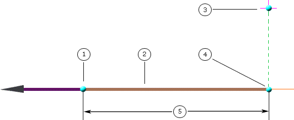
You can also use work points outside the connection axis, but it is not recommended. Using such work points, Autodesk Inventor calculates the perpendicular root of the work point on the connection axis, and then the MaxEP transforms to the distance between the connection point and the perpendicular root.
The following planar draft illustrates how a work point outside the connection axis defines the MaxEP:

1 - Connection point; 2 - Connection axis and direction; 3 - Work point outside the connection axis; 4 - Perpendicular root of the work point; 5 - MaxEP
