
Model Based Definition (MBD) Enhancements (What's new in 2027)
Check out the improvements made to 3D annotations and model based definitions.
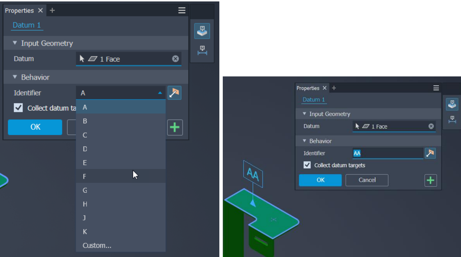
Datum Identifier
Support for creating 3DA Datum Identifier in Part and Assembly environments is added in this release of Inventor.
Change the identifier label by selecting identifiers from the drop-down menu or entering an identifier in the edit field.
You can select only planar faces when placing the Datum Identifier, and only one datum identifier can be created on the same planar face.
Use the Select Annotation option to attach Datum Identifier to the 3DA.
In the Datum Identifier dialog, first, use Input Geometry to select/deselect geometry based on the active selection type. Then, use Select Faces for Non-Feature of Size ![]() . For Feature of Size
. For Feature of Size ![]() use Select Dimension. The Toggle alignment button to flip the position of the Datum ID attached to the Linear/Angular 3DA is enabled for Feature of Size only.
use Select Dimension. The Toggle alignment button to flip the position of the Datum ID attached to the Linear/Angular 3DA is enabled for Feature of Size only.
It's supported for the following annotations:
- Linear Dimension (only for annotations created between two faces)
- Angular Dimension (only for annotations created between two faces)
- Diameter Dimension
- Radius Dimension
- Hole Note
- Thread Note
Datum Target
You can now create 3DA Datum Target also in Assemblies and Weldments.
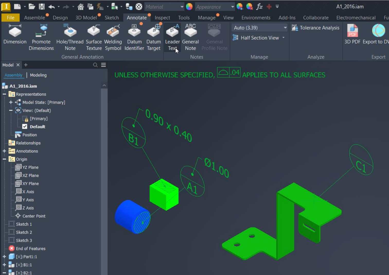
General Profile Note
Also, you can now create General Profile Notes in Assemblies and Weldments.
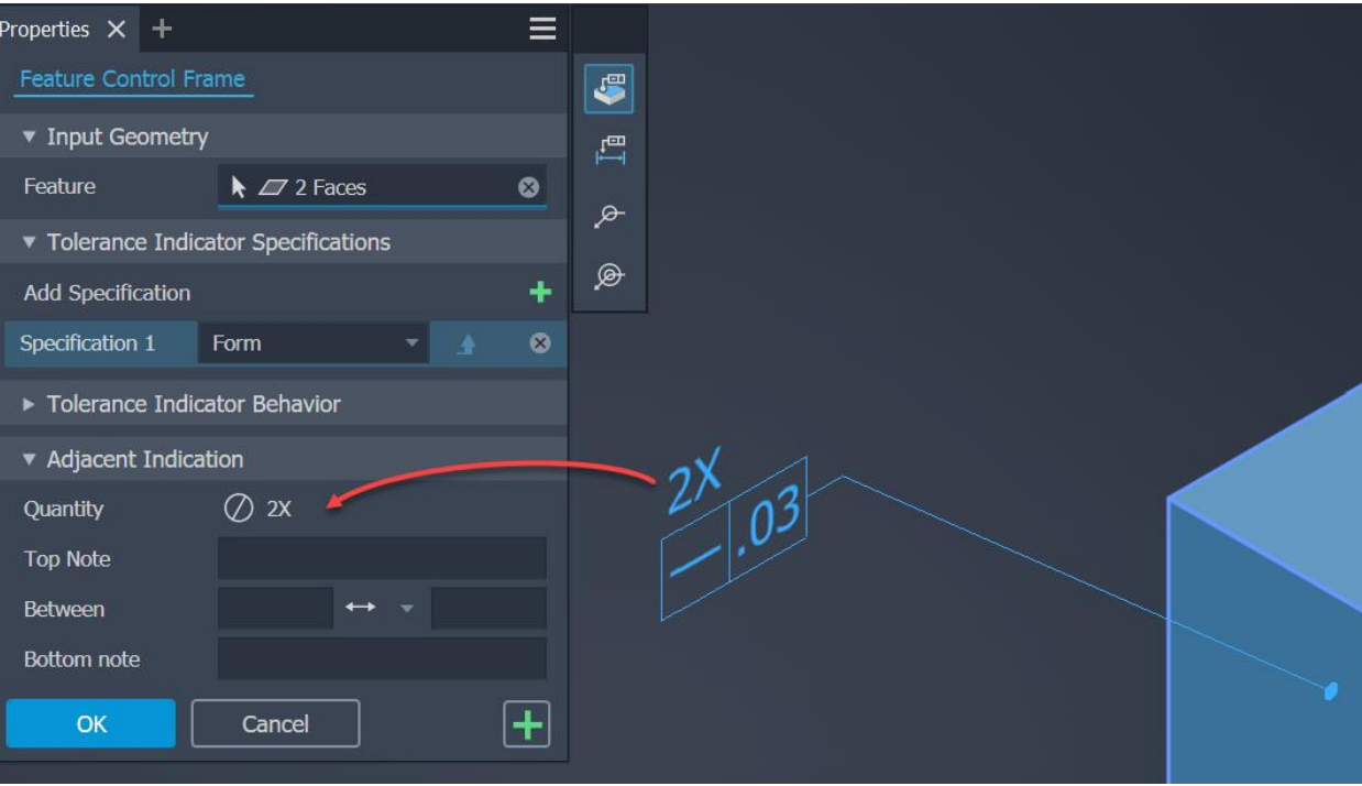
Feature Control Frame
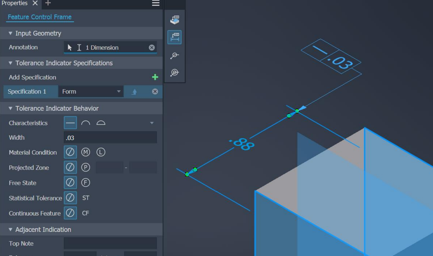
Use the new property panel to create feature control frames.
First, select or unselect geometry based on the active selection type. There are 4 selection types available:
- Integral Feature
- Derived Feature
- All Around
- All Over
Use the Tolerance Indicator Section to set from 1 to 3 specifications. Four specification types are supported:
- Form
- Orientation
- Location
- Run out
Their availability depends on the active selection type and selected geometries.
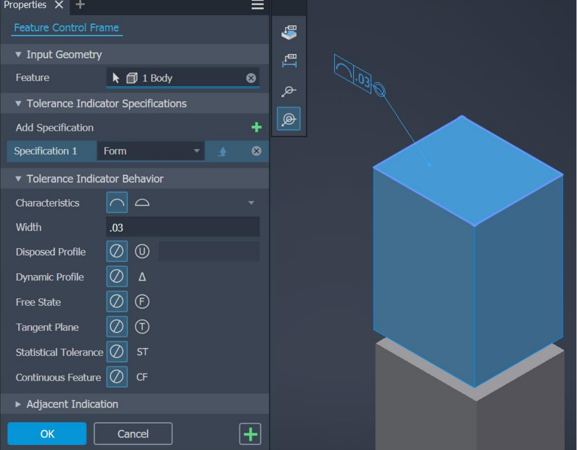
The Tolerance Indicator Behavior section lists symbols for available geometric characteristics, and it depends on the selected geometry. Note that ASME and ISO standards have their own indicators.
Integral Feature
With an active first selection type, you can select multiple geometries. The first selected geometry filters out other types of geometry, so only the selected geometry type can be selected for multi-selection. If more than one geometry is selected, the quantity is shown above the feature control frame and in the property panel.
Annotation Selection Type
Activate the selection type and derived features will be enabled. Datum geometry is shown in the preview.
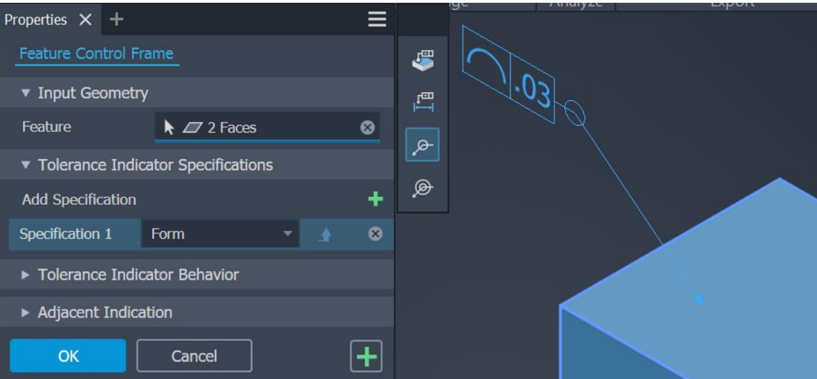
All Around Selection Type
Activate the selection type to select one face or multiple faces of various type of geometry. If needed, enable the Quantity using the Unrestricted Settings.
All Over Selection TYpe
Activate the selection type to select one face and all the faces from the selected body are included in the selection.
Top and Bottom node
You can add the top and bottom nodes in the feature control frames. Depending on the active annotation standard, the position for Between and Notes is set either in the dialog or in the canvas.
Composite Feature Annotation
In the property panel, in the Tolerance Indicator Specifications group, for each specification a drop-down menu is available with controls to select GD&T specifications. Note that this option isn't available for the first specification in the feature control frame. In the canvas, composite annotations will merge geometric characteristic symbols into one symbol.
ASME Standard support
ASME standard is supported in feature control frame.
For more information see About 3D Annotation and Model-Based Definition and To Work with General Annotations.