
Intermediate fiber orientation tensor result
This new result shows how the probability of fiber alignment in a specific direction evolves over the injection cycle.
Available for both a thermoplastic injection molded and a thermoplastic overmolded part, this result is for analyses that includes a Fill or a Fill+Pack analysis.
The following mesh types are supported:
 3D
3D Dual Domain
 Midplane
The Intermediate fiber orientation tensor result is generated when:
- A fiber filled material is selected for the part
- The Fiber orientation analysis if fiber material option on the Process Settings Wizard - Fill Settings dialog is enabled.
- The Output intermediate fiber orientation results option on the Fiber Solver Parameters dialog is enabled.
The Intermediate fiber orientation tensor result shows the probability of fibers aligning in a specified direction over time.
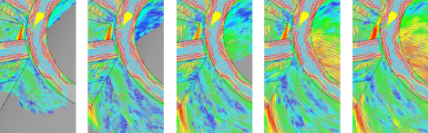
Fig 1: Intermediate fiber orientation tensor over time
Figure 1 shows the increase and then decrease of blue (low probability) tensors. This illustrates how the fiber orientation tensor result changes through the injection cycle.
Midplane and Dual Domain analyses can also show the fiber orientation tensor at different positions through the thickness of the part at intermediate times if the profiled results output has also been enabled. A 3D result can only be displayed on the surface or a cutting plane.
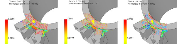
Fig 2: Intermediate fiber orientation tensor through thickness
By default, the tensors are shown in their principal direction - the direction in which most fibers align. The tensor components can also be displayed in relation to a Global Co-ordinate system or a user defined Local Co-ordinate system.
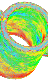
Fig 3: Intermediate fiber orientation tensor in the principal direction
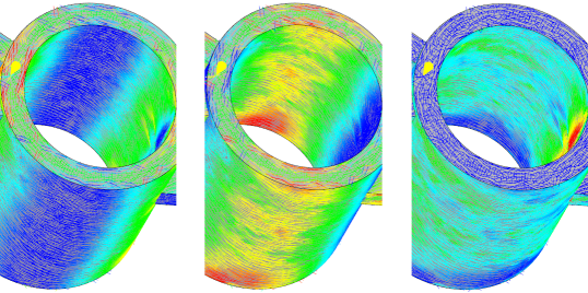
Fig 4: Intermediate fiber orientation for the same result, but in the Txx, Tyy, Tzz orientations for the Global Co-ordinate system