The path where the examples are stored has changed. They are now at
C:\ProgramData\Autodesk\ATU\ATU-Examples\.
The path where the examples are stored has changed. They are now at
C:\ProgramData\Autodesk\ATU\ATU-Examples\.
The buildstyle project is available at C:\ProgramData\Autodesk\ATU\ATU-Examples\buildstyles\Demonstration\slcExport\.
Overview
The idea of this implementation is to have different types of toolpaths that are printed separately in the following order:
- SUPPORT
- DOWN_CONTOUR
- UPPER_CONTOUR
- CONTOUR
- DOWN_FILL
- UPPER_FILL
- FILL
Each toolpath type is also geographically organized. The idea is to print against the gas flow direction, so that chips are forced to land on areas which have already been built (a mechanical operation, at the beginning of the next layer will sweep them away from the part). The direction can be changed by a parameter.
The algorithm splits up the platform into areas:

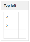
Depending on the direction parameter, only one field is selected at first:
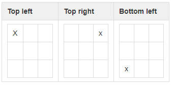
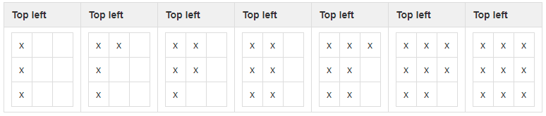
Geometry that is completely covered by this region is printed first. Now a new cell is added to the selection:
New geometry may be printed as well. This process continues until all regions are accounted for.
Build order visualization
| Small blocks | Big block (All geometry fits into one block) |
|---|---|
|
|
Parameters
The toolpath organization can be parameterized using the following parameters:
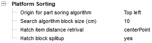
| Parameter | Description |
|---|---|
| Origin | This option sets an origin. Parts that are nearer to this origin are built before parts which are farther away from it. |
| Block size | The platform can be split up into areas. These areas are used to identify the build order of geometry. |
| Distance retrieval | The distance to origin can be determined by the center of the bounding boxes of geometries or by edges of bounding boxes of geometries. |
| Split up | This option splits up grouped toolpath entries and organizes every geometry. |
Implementation
The implementation is split up between the toolpath creation and the postprocessing step:
Toolpath creation
Before we start looking at the actual implementation, let's recall the toolpath object types:
- bsHatch
- bsHatchBlock
- bsHatchInfo
Each layer provides a bsHatch instance, which is used to add toolpaths. New bsHatch instances can be created and merged into the provided one. In the end, the provided bsHatch instance contains all toolpaths of the current layer as a list of bsHatchBlock instances. Each bsHatchBlock instance is a grouped set of toolpath vectors.
Later, at the postprocessing step, the toolpath geometry is queried using a bsPolylineIterator. Each bsHatchBlock instance will be one bsPolyline instance and it won't be possible to split up toolpaths any further. In some cases, it might be useful to operate on each line instead of each bsHatchBlock instance (which may contain a lot of lines). A parameter (Hatch block split-up) can be used to switch between these toolpath representations. An advantage of that splitting is that every geometry element can be reorganized later on. The disadvantage is that no regional or pattern specific dependency between all these lines is preserved and the reorganization may lead to unwanted jumps between areas that were logically grouped before.
| Grouped blocks example | Non-grouped example |
|---|---|

|

|
The splitting is done at Toolpath/closed_geometry.js:
Each bsHatchBlock, which contains non-continuous paths, is split up into bsHatchBlock instances for each line by copying the start and endpoint coordinates. If custom toolpath attributes exists, those attributes could also be copied at this processing step.
if( hatchSplitUp ){
  var hatchBlockIt = tempHatch.getHatchBlockIterator();

  resultHatch = new HATCH.bsHatch();
  while( hatchBlockIt.isValid() ){
    if( ! hatchBlockIt.get().isContinuousPath() ){
      for( var pIdx=0; pIdx < hatchBlockIt.get().getPointCount(); pIdx += 2){
        var newBlock = new HATCH_BLOCK.bsHatchBlock();
        newBlock.appendPoint(hatchBlockIt.get().getPoint(pIdx));
        newBlock.appendPoint(hatchBlockIt.get().getPoint(pIdx+1));
        resultHatch.addHatchBlock(newBlock);
      }
    } else{
      resultHatch.addHatchBlock(hatchBlockIt.get().clone());
    }
    hatchBlockIt.next();
  }
}
Hatch pattern generation
Each hatch pattern is already organized based upon the platform origin, so that all patterns (if possible) are built from the nearest distance from the origin to the farthest distance using the pathReordering function.
/* Creates the hatch pattern for the inner island */
resultStripes.hatchExt(tempHatch,
                       platformOrientationPoint,
                       surfaceDistance,
                       currentAngle,
                       HATCH.nHatchFlagFixedOrigin | HATCH.nHatchFlagAlternating);

tempHatch.pathReordering(platformOrientationPoint, HATCH.nSortFlagUseHotSpot | HATCH.nSortFlagShortestPath | HATCH.nSortFlagFlipOrientation);
Toolpath attributes
Each toolpath entry is tagged with a contour type attribute. This is used later to print toolpaths of certain types before or after toolpaths of a different type.
/************************************************************
 * CONSTANTS
 *********************************************************** */
exports.CONTOUR_TYPE_SUPPORT        = 11;
exports.CONTOUR_TYPE_CONTOUR        = 22;
exports.CONTOUR_TYPE_UPPER_CONTOUR  = 33;
exports.CONTOUR_TYPE_DOWN_CONTOUR   = 44;
exports.CONTOUR_TYPE_UPPER_FILL     = 55;
exports.CONTOUR_TYPE_DOWN_FILL      = 66;
exports.CONTOUR_TYPE_FILL           = 77;

.
.
.

toolpath.setAttributeInt('GeometryType', TOOLPATH.CONTOUR_TYPE_CONTOUR);
Layer post-processing
At this point we retrieve tagged toolpaths at a user defined granularity. Now the toolpath elements have to be sorted. Each element already has a default sort value, which is called _processing_order. It is an attribute that can also be seen at the toolpath preview:
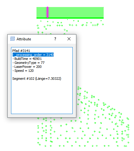
By manipulating these attributes, it is possible to change the toolpath processing order using Postprocessing/postprocessing.js:
After determination of the overall platform boundaries, the elements are sorted and the sort attribute gets updated:
exports.postprocessLayerStack = function(logger,
                                         modelData,
                                         progress,
                                         layerStartNo,
                                         layerEndNo)
{
  logger.addLogMessage('');
  logger.addLogMessage('Postprocessing layerstack');
  logger.addLogMessage('');

  progress.initSteps(5);

  var layerThickness    = modelData.getLayerThickness();
  var zUnit             =  modelData.getZUnit();
  var overallBoundaries = null;

  for( var modelIndex=0; modelIndex < modelData.getModelCount() && !progress.cancelled(); modelIndex++ ){
    var currentModel = modelData.getModel(modelIndex);

    var shadowIslands = new ISLAND.bsIsland();
    currentModel.createShadowIsland(shadowIslands);

    var newBounds = shadowIslands.getBounds();

    if( modelIndex == 0 ){
      overallBoundaries = newBounds.clone();
    }
    else{
      if( newBounds.minX < overallBoundaries.minX ){
        overallBoundaries.minX = newBounds.minX;
      }
      if( newBounds.minY < overallBoundaries.minY ){
        overallBoundaries.minY = newBounds.minY;
      }
      if( newBounds.maxX > overallBoundaries.maxX ){
        overallBoundaries.maxX = newBounds.maxX;
      }
      if( newBounds.maxY > overallBoundaries.maxY ){
        overallBoundaries.maxY = newBounds.maxY;
      }
    }
  }
  progress.step(1);

  logger.addLogMessageWithValue('Scene bounds minX', overallBoundaries.minX);
  logger.addLogMessageWithValue('Scene bounds maxX', overallBoundaries.maxX);
  logger.addLogMessageWithValue('Scene bounds minY', overallBoundaries.minY);
  logger.addLogMessageWithValue('Scene bounds maxY', overallBoundaries.maxY);

  // For safety, we add border space
  overallBoundaries.minX = overallBoundaries.minX - 0.1;
  overallBoundaries.maxX = overallBoundaries.maxX + 0.1;
  overallBoundaries.minY = overallBoundaries.minY - 0.1;
  overallBoundaries.maxY = overallBoundaries.maxY + 0.1;

  // Start exposure vector sorting.
  for( var curLayerNo=layerStartNo; curLayerNo <= layerEndNo && !progress.cancelled(); curLayerNo++){
    logger.addLogMessageWithValue('Postprocessing layer', curLayerNo);
    var sortedGeometry = GEO_SORTER.getSortedExposureData(logger, modelData, curLayerNo, overallBoundaries, progress)
    if( sortedGeometry != null ){
      for( var polyItIdx=0; polyItIdx < sortedGeometry.length; polyItIdx++ ){
        sortedGeometry[polyItIdx].setAttributeInt('_processing_order', polyItIdx);
      }
    }
  }

  progress.update(100);
}
The sorting result can be visualized using the animation option of the exposure preview widget: