

Set the build plate properties and dimensions in the Build Plate dialog.
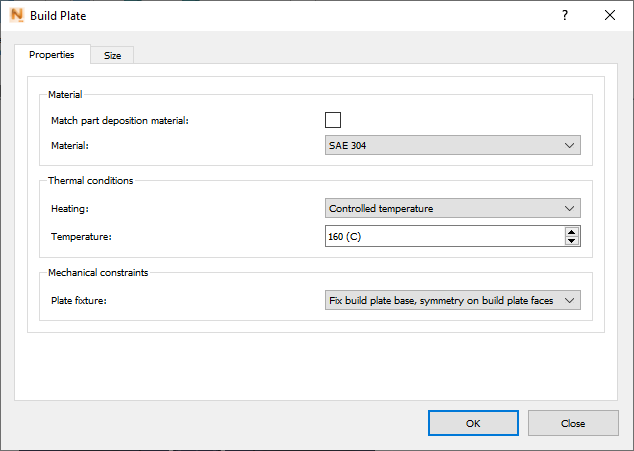
On the Properties tab, if you deselect Match Part Deposition Material, a Material field appears, in which you can choose a different material from the list.
Heating:
- None – build plate temperature is initialized at the ambient temperature
- Initial Temperature – simulates build plate preheating by setting all the build plate nodes to the specified temperature.
- Controlled Temperature – maintains a constant temperature at the base of the build plate the during the entire build.
Plate Fixture:
- Fix Build Plate Base, Symmetry on Build Plate Faces – constrains nodes at the center of the build plate in X, Y, and Z directions, and constrains all other build plate nodes in the Z direction.
- Simulate Bolt Release – adds an additional time step to simulate removing the bolts from the build plate after cooling. This is recommended only when simulating an entire build plate to be representative of the bolt removal process. This option is recommended when using a custom build plate geometry.
- Fix the Center of the Build Plate – constrains only the build plate center, which is used to model the case where the build plate is not fixed to the build platform, but is held in place merely by gravity and frictional forces.
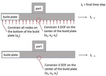
These constraints options are illustrated in the figures below. The constraints during processing are shown in the top figure, with the base of the build plate being well constrained in the Z direction, as well as constraints in the X, Y, and Z direction at the center of the build plate. The lower figure shows the mechanical model constraints with the Simulate Bolt Release, after process modeling completes, cool down and the optional Structural Plasticity step. This option leaves just the constraints at the center of the build plate base, allowing the rest of the build plate to distort. These are also the same constraints used for the Fix the Center of the Build Plate option during the entire process.
Build Plate Sizing
Adjustment fields for the X, Y, and Z dimensions are available on the Size tab. This tab does not appear if you import a custom build plate geometry for the simulation. The Length settings for X and Y can be used to define a build plate region to mesh while the Z control is for setting the build plate thickness. If you want the build plate to be a rectangle the same size as the model's bounding box, click Snap to X and Y. Using these settings will override the build plate size established using the Machine model setting in the Machine dialog.
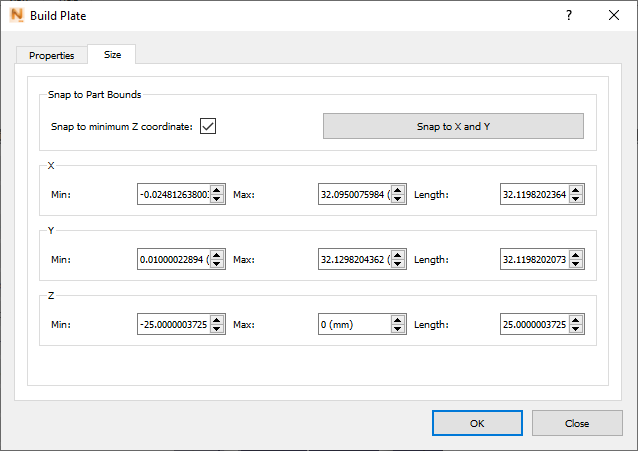
If the Snap to minimum Z coordinate option is selected, the part sits directly on top of the build plate. If you want the part to sink into the build plate, deselect this option, and use the Z Max control to raise the top of the build plate.
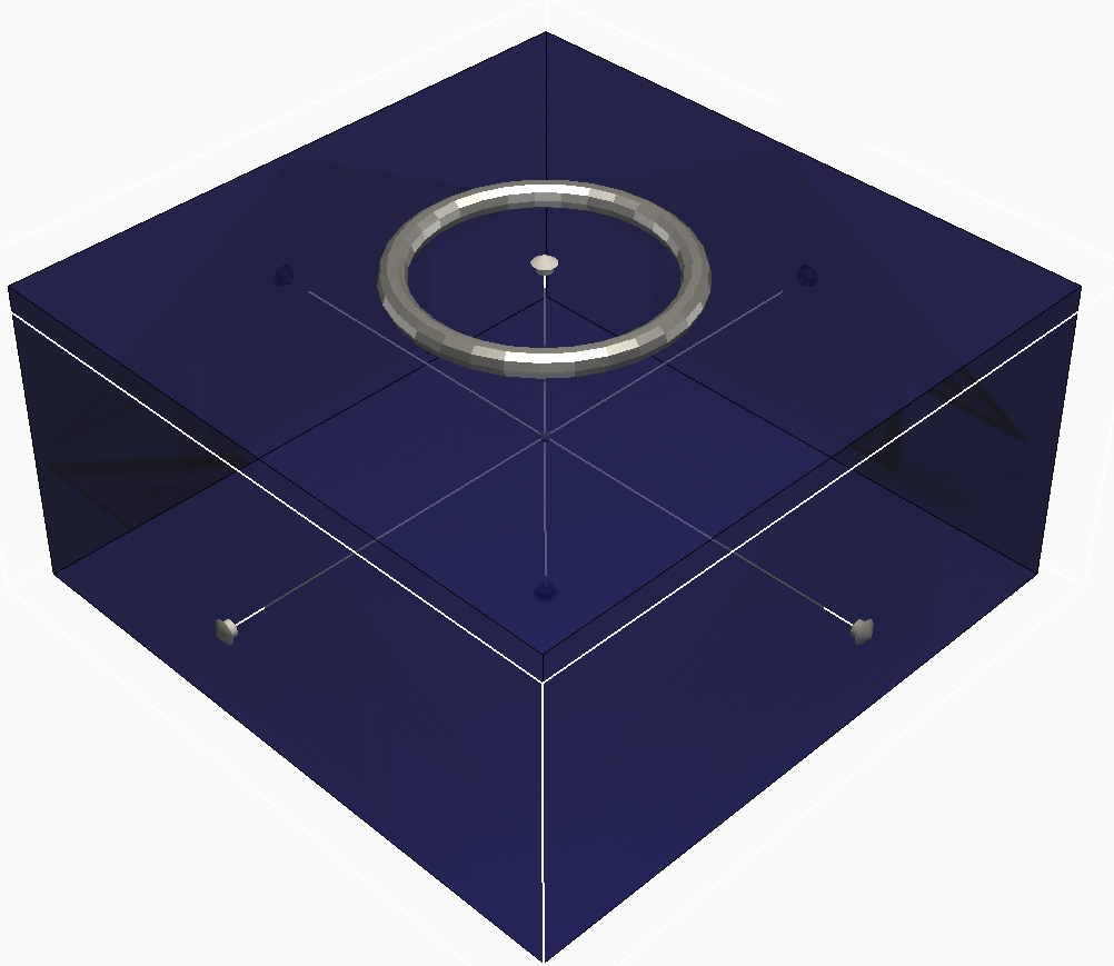
While the Build Plate dialog is open, a knob appears on each axis that you can use to manually adjust the build plate dimensions.