
In this task, we select materials and material properties for the three parts of this assembly, apply physical properties (idealizations) to the parts, and mesh the model.
To define materials
- In the Model tree, right-click .
- In the Material dialog, click Select Material. The Material DB dialog will show some available material libraries.
- Expand the
Autodesk Material Library, select
Copper, and click
OK. This material will be chosen for the Billet.
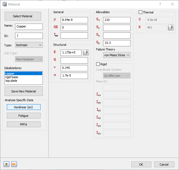
- Click the Nonlinear button, then in the Nonlinear Material Data dialog select Elasto-Plastic (Bi-Linear). Click OK in this dialog and OK to close the Material dialog.
- In the Model tree, right-click again.
- In the Material dialog, click Select Material, expand the Autodesk Material Library, select Alloy Steel, and in the Material dialog, rename it to Alloy Steel_Base Rigid.
- In the third column of the Material dialog, select Rigid. Doing this tells the analysis code to treat the bottom base plate part as a rigid body. The code will compute the center of mass and inertial properties of the part.
- In the lower left corner of the
Material dialog, click the Duplicate
 button. The Alloy Steel_Rigid Base material is added to the model, and the Material dialog remains open for definition of a third material.
- Click Select Material, expand the Autodesk Material Library, and again select Alloy Steel.
- In the Material dialog, rename the material to Alloy Steel_Top Plate, and deselect the Rigid option.
- Click OK to close the dialog.
To define idealizations
- In the Model tree, under Idealizations, delete any existing Solid materials, then right-click .
- In the
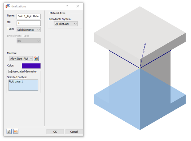
Idealizations dialog, set the following values:
- Name: Solid 1_Rigid Plate
- Type: Solid Elements
- Material: Alloy Steel_Base Rigid
- Select
Associated Geometry, then click the base of the model to apply this idealization.
- In the lower left of the
Idealizations dialog, click the New
 button and set the following values for the Copper billet:
- Name: Solid 2_Copper Billet
- Type: Solid Elements
- Material: Copper
- Select Associated Geometry, then click the middle part of the model to apply this idealization.
- Again click the New
button and set the following values for the Top Plate:
- Name: Solid 3_Top Plate
- Type: Solid Elements
- Material: Alloy Steel_Top Plate
- Select Associated Geometry, then click the top part of the model to apply this idealization.
- Click OK to close the Idealizations dialog.
To mesh the model
- In the
Assembly tree, right-click
.
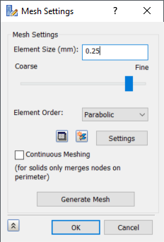
- In the Mesh Settings dialog, set Element Size to 0.25 mm, Element Order to Parabolic, deselect Continuous Meshing, then click Generate Mesh to generate the mesh.
- Click OK to close the dialog.