
Apply Constraints
- In the tree view, right-click on Constraints and select New.
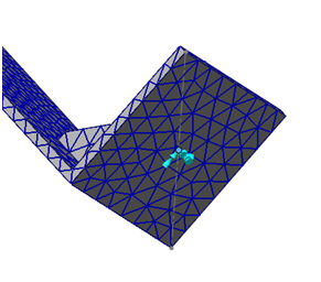
- Select the point at the base of the model to be fixed in all 6 degrees of freedom.
 In this release, the 3D sketch point is not supported. Currently, you can use the 3D wire sketch segment to select the end point as 3D sketch point.
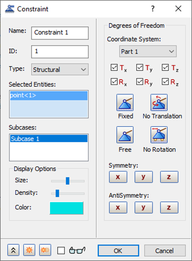
- Click OK to accept the default fixed constraint settings.
Apply Loads
- Right-click on Loads and select New.
- Select
Enforced Motion in the
Type drop-down menu and
Acceleration in the
Sub Type drop-down menu.
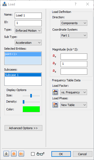
- Click the constrained point at the base of the structure.
- Type in 1.0 in the ay box under Load Definition.
- Click the
 New Table button next to the
Load Factor drop-down, under the
Frequency Table Data section.
New Table button next to the
Load Factor drop-down, under the
Frequency Table Data section.
- Define your table as shown below, by double-clicking in the cells. Notice that the values are along the frequency of interest. Change the
Name to
vs. Frequency.
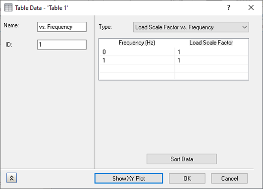
- Choose Load Scale Factor vs. Frequency from the drop-down menu.
- Click the
Show XY Plot button to see the plot. It should look as shown below.
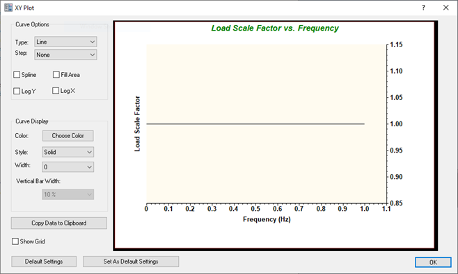
- Click OK on the XY Plot dialog.
- Click OK on the Table Data – ‘Table 1' dialog.
- Click OK on the Load dialog.
With enforced motion loads (displacement, velocity, and acceleration), the direction that is desired to be enforced must be constrained. This may seem awkward, but just remember that enforced motion is constrained motion.
Define the Rigid Element
- In the
Model tree, right-click on
Connectors and select
New.
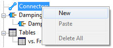
- In the
Type drop-down menu, select
Rigid Body.
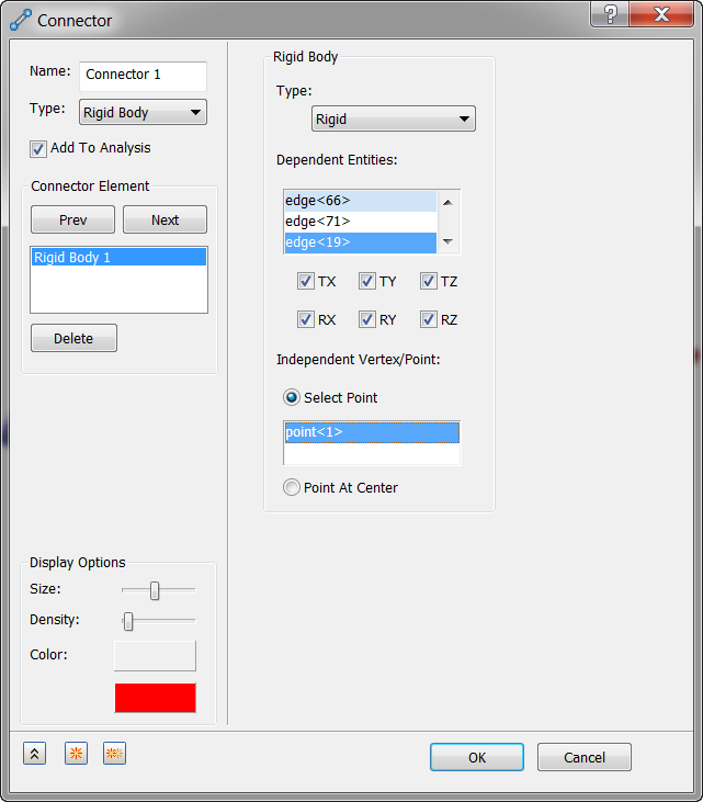
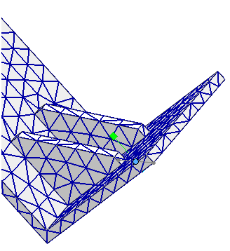
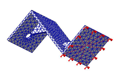
- Click in the Independent Vertex/Point to activate it, then click the same sketch point for which the constraint and load are defined; for Dependent Entities, click the four edges around the bottom of the bracket.
- Click
OK to accept the changes. Your model should look as shown below.
Define the Modal Setup
Modal frequency response solutions need modal information to solve the equations of motion.
- In the tree view, under Subcases, right-click .
- Type 40 for Number of Modes.
- Click OK to accept the changes.
You defined 40 modes in order to achieve enough modal information to get a good answer. This was found by running a normal modes analysis and looking at the Percent Modal Mass table found in the Autodesk Nastran Output file (*.OUT). With 40 modes, the table looked as shown below.
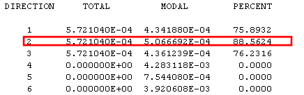
Notice that there is 88% in the 2 direction. We want more than 80% in this direction since this is the direction we are giving base excitation to. You can view this output (*.OUT) file with any text editor, such as Notepad.
Define the Dynamics Setup
For modal frequency response solutions, the dynamics setup options are a little different. In this particular analysis, you are going to only be interested in the first flexural mode of the structure do to the frequency dependent loading.
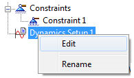
- In the tree view, right-click on
Dynamics Setup 1 and select
Edit.
- Click the Cluster between Modes checkbox and select Linear under Increment.
- For Lowest Frequency enter 100.0 and for Highest Frequency enter 350.0.
- Enter 10 in the Number of Points between Modes.
- The
Bias Factor should be set to a default value of
1.
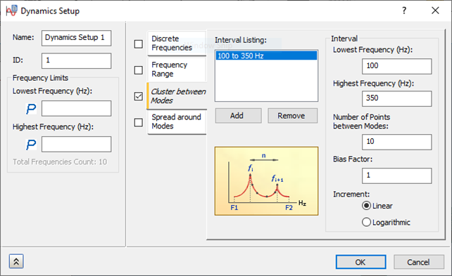
- Click OK to accept the changes.
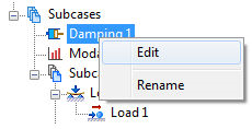
Define the Damping
- In the tree view, right-click
.
- Uncheck Structural Damping if it is checked by default.
- Select the Modal Damping checkbox and select Constant from the Type drop-down under Modal Damping.
- Select Structural from the Damping Definition drop-down menu.
- Enter
0.05 for the
Damping Value.
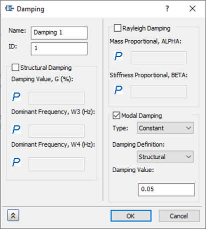
- Click OK to accept the changes.