
Map the coordinate system of the measuring device to the coordinate system of the CAD model.
The Transform Matrix dialog is a common dialog. The options change depending on how the transform is used.
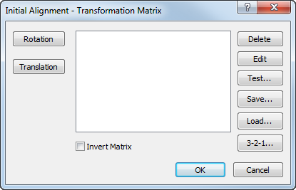
For example, the CAD - Transform Matrix dialog displays a Mirror and Scale button. The Initial Alignment - Transformation Matrix dialog displays a 3-2-1 button.
The dialog can contain the following options:
- Rotation — Rotate the model around a specified axis.
- Translation — Move the model by a specified distance along the X, Y, and Z axes.
- Scale — Increase or decreases the size of the model in the CAD view.
- Mirror — Invert the CAD model in a specified plane.
- Transform List — Sequence the rotation, translation, scale, and mirror composition. You can select and drag items to change the order.
- Delete — Delete the selected transformation.
- Edit — Edit the selected transformation.
- Test — Compare the coordinates of a specified location before and after the transformation.
- Save — Save the transformation as a transformation matrix (.mat) file.
-
Load — Load a previously saved transformation matrix or a workplane from a CAD file.
- Load a .mat file or model file that contains the transformations you want to use. Any existing transformations are deleted.
- If the model file contains workplanes, you can select the workplane you want to work with.
- 3-2-1 — Create an initial alignment between the Machine Datum and the (PCS) CAD Datum.
Note: The 3-2-1 button is not available in OMV.
- Invert Matrix — Invert the transformation matrix.
For example, inverting a matrix that has a scaling of 2 and a rotation of 30 degrees about X produces a rotation of -30 degrees about X and a scaling of 0.5.
Rotation dialog
Rotate the model in a specified axis.
- Axis rotation options are:
- Around X (YZ Plane) — 0 degrees is along the Y axis; 90 degrees is along the Z axis.
- Around Y (ZX Plane) — 0 degrees is along the Z axis; 90 degrees is along the X axis.
- Around Z (XY Plane) — 0 degrees is along the X axis; 90 degrees is along the Y axis.
- Angle (in degrees) — specifies the angle you want to rotate the model in the Axis.
Translation dialog
Move the model along the major axes.
- The
X,
Y, and
Z boxes specify the distance you want to move the model in each axis.
The
 button inverts the axis values.
Mirror dialog
Mirror the model.
- Plane — Plane in which you want to mirror the CAD model.
- Coordinate — Position on the selected axis about which you want to mirror the model.
Scale dialog
Increase or decrease the size of the model.
- X, Y, and Z — Location of the centre of expansion relative to the PCS datum.
- Factor — Factor to scale the model.
For example, to double the size of the model enter 2.
- The
 button changes the specified
Factor to its reciprocal.
button changes the specified
Factor to its reciprocal.
For example, a Factor of 4 changes to 0.25.