
Use this option to define fire resistance parameters of the steel member type for the Eurocode 3 (2005) code. Access the parameters by clicking the Fire button in the Member Definition - Parameters dialog.
The option allows for the design and verification of steel members of an arbitrary section according to the following guidelines:
- The European code EC3 EN 1993-1-2:2005
- The official document 3 of the ECCS Technical Committee 'Model Code of Fire Engineering' - First Edition, May 2001.
The scope of the code includes calculations of steel members loaded with an arbitrary set of internal forces (N,Vy,Vz,Mx,My,Mz). As the documents recommend, calculations are performed using one of the following methods: resistance domain, temperature/time domain or time domain.
Resistance domain
The resistance domain consists of the following:
- Evaluating the maximal temperature of an element Oa,max for defined fire parameters and the required time resistance treq,
- Verifying the strength of the element considering the change of steel strength parameters at the higher temperature.
- Verification condition applied: Ed,fi < Rd,fi.
Temperature / time domain
The temperature / time domain consists of the following:
Evaluating (directly or by means of the iterative method) the critical temperature of a member Oa,Cr at which its resistance is depleted; if the element temperature Oa,max, evaluated analogously as using the resistance method, does not exceed the critical temperature Oa,Cr, then the element is qualified as correct Oa,max < Oa,cr.
Time domain
The time domain consists in evaluating the maximal time of member fire resistance tfi,max for fire parameters defined by the user; calculated temperature is compared to the required treq temperature; a member is correct if the criterion treq > tfi,max is met.
A calculation method may be chosen in the Configuration dialog.
Users can evaluate the maximal temperature of surfaces of elements protected and unprotected against a direct action of fire. Robot offers a database of the most-frequently-used insulating materials according to the Explanatory Document for ECCS N 89 - <Euro-Nomogram> Fire Resistance of Steel Structures; new insulating materials can also be added to the database.
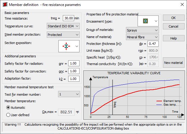
The dialog for the definition of fire parameters includes options to enable the simulation of the temperature of any steel member defined in an analyzed model. The diagram in the lower part of the dialog illustrates variability of the temperature of a selected element in time (in the interval of 0-120 minutes). The temperature of a chosen member for the currently-defined time resistance is also displayed. The diagram is automatically updated after changing any parameters.
Fire resistance calculations of steel elements are started after activating the Fire calculations option in the Configuration dialog. The Configuration dialog allows selecting a code which will be the basis for the analysis (general guidelines of the EN 1993-1-2 code or recommendations of the ECCS Technical Committee).
The following parameters are defined :
Basic parameters
- The Basic parameters field is used to determine:
Time resistance - a required time of fire resistance in minutes (the maximum fire resistance time is 120 min.)
Temperature curve - select a curve for evaluating the temperature of gases resulting from the fire: available curves:
- Standard ISO 834
- external fire
- hydrocarbon fire
- smoldering fire
Steel member protection - select if the member will be Protected or Unprotected
Section exposition - choose from the selection list an icon for an element exposed on 3 sides, on all sides or only with the lower flange exposed
Protected element
- The Properties of fire protection material field is used to determine:
Encasement type - selection of encasement types; 2 basic types are available: Hollow and Contour
Group of materials - definition of a group of base materials, e.g. boards, plasters, paints
Name of material - definition of one of the materials belonging to a selected material group, e.g. acrylic paint
Protection thickness - definition of a thickness of an insulating layer protecting a column; default values depend on a material chosen from the database
The parameters Unit mass, Specific heat, Thermal conductivity are given as additional information for an insulating material type chosen from the database
In the case of a protected element, it is possible to define a new type of the insulating material and to add it to the database of insulating materials; it can be done in the Member definition - new insulating materials dialog opened by clicking the New material button
Unprotected element
- The Thermal properties of steel field is used to determine:
Unit mass - a default value roa = 7850 kg/m3
Coefficient of heat transfer by convection - a coefficient depending on a selected temperature curve
Configuration factor - a factor which allows accounting for an element shape and position in a structure (more about definition of this factor can be found in recommendations of the ECCS Technical Committee, point III.3); the interval of the parameter variability: <0.01,1>
Member surface emissivity - the interval of the parameter variability: <0.01,1>
Fire emissivity - the interval of the parameter variability: <0.01,1>
Ignore the 'shadow' effect - if this option is selected, then calculations of the ksh factor, used for evaluating the critical temperature of steel, are not performed - in such a situation, the factor will equal 1.0 (it refers only to calculations according to the EN 1993-1-2 code)
- The Additional parameters field is used to determine:
Safety factor for radiation - a default value = 1.0
Safety factor for convection - a default value = 1.0
Safety factor for fire situation - a default value = 1.0
Adaptation factor - a value that accounts for non-uniform heat flow through the section of a beam in bending in fire conditions; a default value = 0.7
- The Member maximal temperature test field evaluates through testing the maximal temperature on the surface of a selected structure member; using sectional parameters of a member and values defined in the above dialog, the maximal temperature that an element will reach after a determined time resistance is calculated; selecting the Member temperature - user-defined option allows the user to omit the automatic evaluation of the element temperature and to define user's own temperature
- The Temperature Variability Curve diagram presents the way the maximal temperature on the member surface changes in time (the red curve); the blue curve illustrates variability of the temperature of gases resulting from fire in time.