Use the option to control the visibility level for a structure; by default, the option is in the bottom left corner of the screen. It lets you select a part of the structure to display. You can also adjust the visibility level for the remaining parts of the structure.
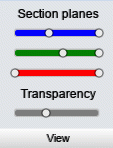
To expand the View option, position the cursor on it; 4 sliders display then (as shown in the image below):
First 3 are Section planes and their colors indicate directions of the coordinate system:
- blue - X axis
- green - Y axis
- red - Z axis.
Each slider has 2 controls (on the right and left side); the controls allow you to move limiting planes that are parallel to the main planes of the coordinate system.

Parts of the structure that are outside the planes display semi-transparent. You can control the transparency level using the fourth slider - Transparency. If you set the transparency value to zero, only the part of the structure, that is between the planes, displays.
Use the View option to:
- Define section planes:
Left Mouse Button Click (LMC) - clicking, holding down and moving a selected control moves a section plane
Right Mouse Button Click (RMC) - clicking, holding down and moving one of the controls of a selected Section planes slider moves simultaneously both controls
- Restore default settings:
LMC - double-clicking a selected Section planes slider restores default settings for the controls of that slider
LMC - double click the View option restores default settings for all controls on the Section planes sliders
- Change the on-screen position:
LMC - clicking and holding down the View option moves an option to any position on the screen
- Enable / disable options:
RMC - clicking the View option blocks the possibility to open or expand the options.
