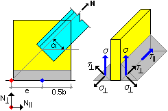
As a connection is verified, the software checks the limit states of the connection:
For bolts that connect a bar to the gusset plate - according to section [3.4.1 Table 3.2]:
- resistance for shear in one plane [Table 3.4]
- bearing pressure resistance Fb,Rd [Table 3.4]
Forces in bolts are calculated according to section [3.12] treating the connection as a lap splice connection loaded with a longitudinal force N and the moment M0
M0 = N * e,
where e = distance of the centroid of a bolt group from the axis of gravity of a bar

For welds that connect a bar to the gusset plate - according to section [4.5.3]
Welds are treated as fillet welds. A connection is treated as a lap splice connection loaded with a longitudinal force N and the moment M0
M0 = N * e,
where e = distance of the centroid of a weld group from the axis of gravity of a bar.
During calculations, the software checks characteristic points of the system of welds where stresses may reach maximal values. The most critical point is selected.
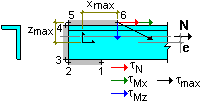
For a bar:
- verification of resistance of tension elements according to section [3.10.3]
- verification of the wall resistance for shear and failure according to section [3.10.2]

Gusset plate - single bar
Plate fixing:
For a bolt connection, identically as for bolts that connect a bar to the gusset plate.
Forces acting on a connection are as follows:
N^ = N * sin(a)
NII = N * cos(a)
M0 = N^ * e,
where e = distance of the centroid of a bolt group from the axis of action of the N^ force
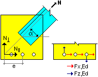
verification of resistance of the plate section weakened by openings according to section [4.1.2]
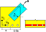
For welds:
- calculation of butt welds according to section [4.6]
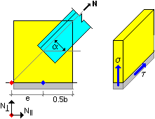
- calculation of fillet welds according to section [4.5.3]; the load is split by half between each of the welds, and calculations are performed for one weld.
