
The model determines the shear studs required to transfer the horizontal shear at the interface between the steel beam and the concrete slab using the provisions of ANSI/AISC 360-10 I3. Shear connectors are assumed to consist of welded headed steel studs with user defined diameter and material strength properties.
Stud counts are determined once the section has been chosen and checked against pre-composite and composite strength requirements.
The individual strength of a stud is based on the minimum of two equations (from ANSI/AISC 360-10 I3.2d):
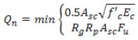
where the placement factor R p is always assumed to be 0.6 ("weak position" placement of the studs). The group factor R g is estimated to be 1.0, and then Q n is recalculated based on the number of rows of studs. If the user has selected the "Proportional R g ", the group factor will be calculated based on the percentage of the beam that has each number of rows. For example, if the number of studs will require 1.5 rows, the R g factor will be half-way between 1.0 (for one row) and 0.8 (for two rows). If "Proportional R g " has not been selected, the number of rows will be rounded up to the next whole number.
Full-composite stud strength
For full-composite strength, the combined strength of the studs must at least equal to the compressive stress in the concrete (or the net stress in the steel, which is the same quantity). Once the strength of each stud Q n is known, the number of studs can be determined. (The actual number of studs required on the beam is twice the number calculated to develop the shear strength - an equal number is needed on either side of the center of the beam).
Partial-composite stud strength
The total moment capacity of the full-composite section may be greater than required. The strength of the section can be lowered (as well as cost) by reducing the number of studs used. Since the amount of stress in the concrete is limited by how much shear stress the studs can develop, the compressive stress in concrete C c will be limited by  in a partially-composite case. After the new concrete stress is known, the rest of the section stresses can be found as before.
The "percentage composite" is defined as:

For partial-composite stud design, the stud count is reduced until:
- The strength of the section falls below the required strength.
- The spacing of the studs exceeds the maximum user setting or code limit.
- The percent composite falls below the user-set minimum or 25 percent.
- Deflections exceed user-set limits (since reducing the stud count lowers the compressive stress in the concrete, the effective moment of inertia I eff(as calculated above) will also lower, increasing deflections).
- Stud placement for final design.
Final stud counts and placement are determined per ANSI/AISC 360-10 I3.2d. Shear studs are provided such that the following conditions are met:
- Shear studs are provided at a maximum spacing of eight times the slab thickness or 36 in (whichever is lesser).
- Minimum number of shear studs required to develop the controlling moment (anywhere along a span) are distributed uniformly between the point of maximum bending moment and the adjacent points of zero moment (on each side of the point of maximum moment).
- Minimum shear studs capable of developing the maximum moment required at any concentrated load (such as a beam framing into a girder, or applied point load) are placed between that load and the nearest point of zero moment (support).
The model investigates the shear stud density required in each region of the moment diagram based on the gradient of the moment diagram, and provides the required density as a uniform stud distribution that meets the above requirements. However, the model will also report a "segmented" stud distribution with studs provided between each support and each concentrated load along the span of a member.