
Add Connections based on Ranges of Applicability
Add connections based on ranges of applicability.
Prerequisite
In order to place connections based on ranges you need to have detailed steel connections with ranges of applicability defined.
This is done after filtering the connection input elements (connection nodes).
How to
The main steps to apply connections based on their ranges of applicability are:
- Get the connection types of a connection family
- Order the connection types alphabetically
- Validate the connection types based on their ranges on each situation (previously filtered connection nodes)
- Prepare filtering results for connection placement
- Create the connection using the
Connection.ByTypenode.
Example
Let's see how to do each of these steps.
1. Get the connection types of a connection family
The node to do this is ConnectionType.ByName. The first input is the connection family name, for example Clip angle.
Tip: In order to place connection types from multiple connection families you can split the input using String.Split by a character, such as semicolon ;.
The second input is the .rvt source file (your library of steel connections). Leave the second input null to use the current Revit model.
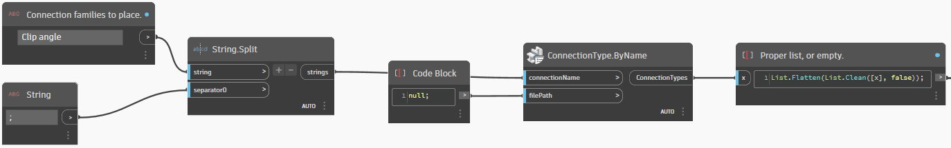
Tip: It is a good practice to make sure the list is clean in order to avoid warnings later in the script by giving a null value when a list is expected. One way this can be done is with a List.Flatten after a List.Clean, as in the above example.
2. Order the connection types alphanumerically
This can be done by using the List.SortByKey Dynamo node on the ConnectionType.TypeName Dynamo node.
 Tip: It is recommended to only order based on the
 ConnectionType.TypeName and not include ConnectionType.ConnectionName to allow mixing multiple connection families such as a standard connection and a custom connection family. For an improved sorting of numbers, a Python node can be applied to the ConnectionType.TypeName such as the one from the provided scripts that validate the ranges of applicability.
3. Validate the connection types based on their ranges on each situation (previously filtered connection nodes)
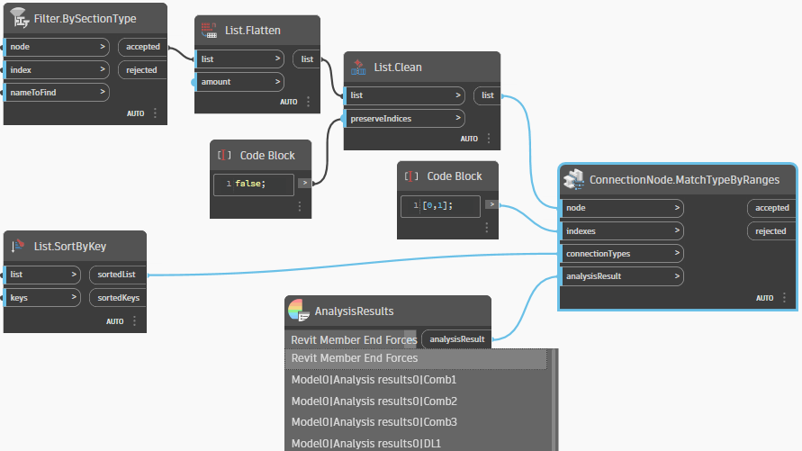
Validation of the connection types is done using the ConnectionNode.MatchTypeByRanges Dynamo node.
The Dynamo node takes as input a connection node or a list of connection nodes, the index or indexes of the structural elements that will be connected, the list of connection types and a source of data for structural analysis results.
The indexes must match the indexes given to Connection.ByType in step 5, and should also match the convention used when filtering the input members.
If there are ranges defined for member end forces of input elements, they will be checked against values from the specified analysis result. For analysis results imported into the Revit model, such as from Robot, a load case, a combination, or an envelope must be chosen. The default is Revit analytical model, called "Revit Member End Forces"
Note: It is necessary to do List.Flatten and List.Clean after the ConnectionNode filtering in order to work with a clean list of appropriate geometrically appropriate situations.
4. Prepare filtering results for connection placement
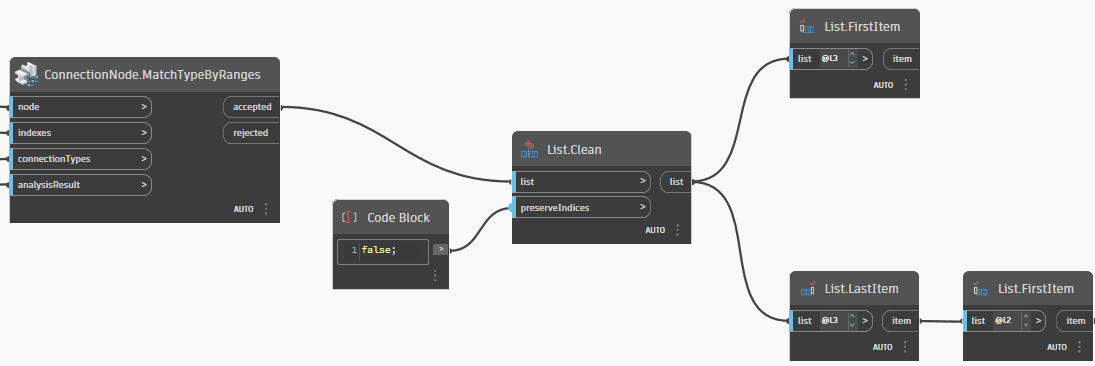
For each item in the resulting list we need to take the first element as the ConnectionNode, and the second element as the list of applicable connection types. We can do this by using List.FirstItem to get the ConnectionNode and List.LastItem to get the list of connection types that have ranges validated for the ConnectionNode.
Note: We recommend to do a List.Clean before in order to work with a clean list and avoid warnings.
Secondly, from the list of applicable connection types we want to chose the first one. We do this by another List.FirstItem.
In this way we will place in our model the first connection type in the previously alphabetically sorted list that has its ranges validated for each specific situation (connection node).
5. Create the connection
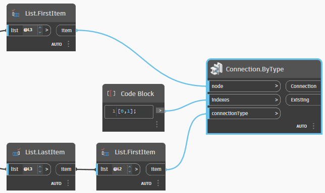
The Dynamo node that you need to add to the script is Connection.ByType. This node is used for placing connections.
Connect the output of the first branch, of the List.FirstItem node, to the first input of Connection.ByType node.
Connect the output of the second branch, of the List.FirstItem node, to the last input of Connectin.ByType node.
Note: The indexes, that is the middle input, need to be the same as at step 3, the validation step.
Optionally you can enhance your script by generating a detailed log file, follow the next step to learn how to use the capabilities delivered with Revit starting with Revit release 2024.
Next step: Generate Detailed Log