
Place a slanted column in a plan view with 2 clicks—one to specify the column start point and one to specify its endpoint.
You define the elevation and offset of each click or use 3D snapping to join to previously placed elements.
- On the ribbon, click
 (Structural Column).
- Structure tab
 Structure panel (Column)
- Architecture tabBuild panelColumn drop-down (Structural Column)
Where is it?
- Structure tab
- Click Modify | Place Structural Column tabPlacement panel
 (Slanted Column).
- On the Properties palette, select a column type from the Type Selector drop-down.
- On the Options Bar, specify the following:
- 1st Click. (Plan view placement only) Select the level for the column start point. Specify an offset for the column end in the text box.
- 2nd Click. (Plan view placement only) Select the level for the column end point. Specify an offset for the column end in the text box.
- 3D Snapping. Select 3D snapping if you want either or both ends of the column to snap to previously placed structural elements. This is the most accurate placement method when placing in sections, elevations, or 3D views.
If modeling in a section, elevation, or 3D view, sketch the column in place.
- In a plan view, click to specify the start point of the column at the level selected for 1st Click.
- Click to specify the endpoint of the column at the level selected for 2nd Click.
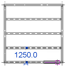
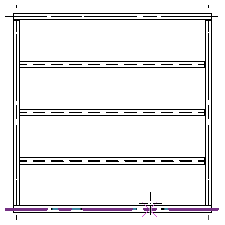
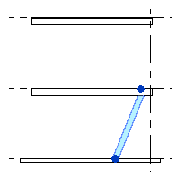
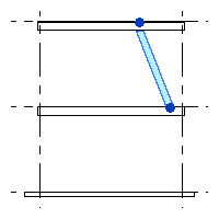
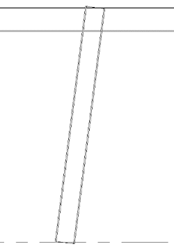
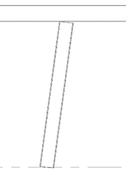
The column is placed, defined by the 2 clicks, their associated levels, and defined offsets. The following illustrations show slanted column placement from the level 2 structural plan of a project using the click locations shown.
| 1st Click: Level 1 and 2nd Click: Level 2 | 1st Click: Level 3 and 2nd Click: Level 2 |
|---|---|
 |
 |
Point to point workflow for slanted columns
When you add a slanted column using the point-to-point workflow, the column's geometry now extends to the end point of the system length.
If you turn off the point-to-point option, the slanted column will adjust to a secondary state. In this state, the column aligns with the bottom of the intersecting beam and attaches to the smallest intersection line.
|
 |
|
 |
See Point to Point Steel Modeling for more information.