Use the automatic shortening option in Structural Settings to create steel element geometry starting from the exact start and end click point.
- Structure tab
 Structure panel

- Manage tab
 Settings panel
 (Structural Settings)
Where is it?
About automatic shortening of steel elements during auto-join
You can toggle the automatic shortening behavior of structural steel elements for new models or, retroactively, for current models with the following steps:
- Click Structure tab
 Structure panel

- Click Manage tab
 Settings panel
 (Structural Settings). The Structural Settings dialog opens.
- In the Structural Settings dialog, click the Structural Steel Elements tab.
- Check the box for Disable automatic shortening of steel elements during auto-join.
Note: If a warning dialog appears, click OK.
- Click OK to save your changes and close the Structural Settings dialog.
or
The steel elements from the drawing will be updated with the point-to-point geometry for existing project elements and for newly created elements.
| Option | Example |
|---|---|
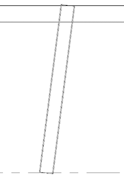
| Steel beams with automatic shortening enabled |
 |
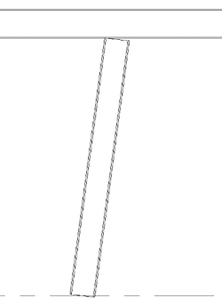
| Steel beams with automatic shortening disabled |
 |
- In the Properties panel, the following values sets changed:
- Start Extension cannot be edited.
- Start Join Cutback is removed from the list.
- The Weight is re-calculated to match the length.
- System Length and Cut Length are now equal.
- Elements can be further edited by using steel modifiers or other Revit features like voids, etc.
- On the ribbon, when selecting a beam, the Change Reference feature is no longer available.
- Columns and slanted columns are not affected by the point-to-point option; the geometry will still be shortened as expected depending on the context.
Point to point workflow for slanted columns
When you add a slanted column using the point-to-point workflow, the column's geometry now extends to the end point of the system length.
If you turn off the point-to-point option, the slanted column will adjust to a secondary state. In this state, the column aligns with the bottom of the intersecting beam and attaches to the smallest intersection line.
|
 |
|
 |
