
After the Generate Layout tool is open, the Generate Layout tab and Options Bar provide the following tools that let you create a layout for your system.
- Edit Layout: Allows you to modify a layout either by repositioning individual layout lines or by combining them.
You combine layout lines by first selecting the layout line that you want to combine and then by dragging its Elbow/End control until the control snaps to an adjacent layout line. The layout line that was modified is automatically removed and additional layout lines are added to represent a physical connection to the component that is associated with the modified layout line. All components that are associated with modified layout lines maintain their original placement. Combining layout lines allows you to redefine your layout so that it corresponds to your design intent.
Note: Only adjacent layout lines can be combined. However, layout lines that connect to system components cannot be modified because they are necessary to connect the component to the layout.Note: A layout line can only be moved up to a tee or cross fitting in one action. You can select the line again, and move it beyond the tee or cross fitting.When using Modify, one custom solution is remembered for the current (modified) layout. If you later use Modify to select a different solution, a message is displayed, asking if you want to overwrite your previous solution.
To modify a layout, click
 (Modify) and select a layout line that you want to relocate or combine. You can then use the following controls:
  Parallel Movement Control: Lets you move an entire layout line along an axis that is perpendicular to the layout line. Additional lines are automatically added when needed to maintain connections in the system. Note that you cannot use this control to overlap layout segments. You must use the Elbow/End Control.
 Junction Controls:
 —Represents a tee.
  —Represents a cross. These junction controls let you move a tee or cross connection between a main and branch segment, left or right, up or down. Movement is limited to the end associated with the Junction Control symbol (see note above).
  Elbow/End Control: Lets you move the intersection between 2 layout lines or the end of a layout line. This control also allows you to combine layout lines. Additional layout lines are automatically added when needed to maintain connections in the system.
 Elevation Control: Indicates the current elevation of the line. Click the elevation control and enter a value to adjust the elevation.
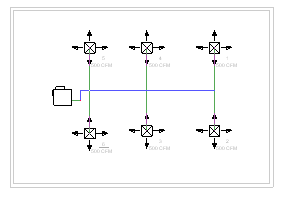
- Solutions: Allows you to select a Solution Type and proposed solutions on the Options Bar. Each layout solution consists of a main (blue) and branches (green). The following solution types are available:
Network: This solution creates a bounding box around the components selected for the duct system, then bases up to 6 solutions on a main segment along the center line for the bounding box, with branches at 90 degree angles from the main segment.
Perimeter: This solution creates a bounding box around the components selected for the system, and proposes 5 potential routing solutions. Four solutions are based on 3 of the 4 sides of the bounding box. The fifth solution is based on all 4 sides.
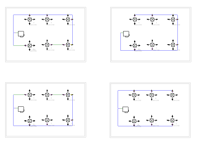
You can specify the Inset value that determines the offset between the bounding box and the components.
Intersections: This solution bases the potential routing on a pair of imaginary lines extending from each connector for the components in the system. Perpendicular lines extend from the connectors. Where the lines from the components intersect are potential junctions in the proposed solution. Up to 8 solutions can be proposed along the shortest paths.
You use the arrow buttons (

 ) to cycle through proposed routing solutions.
 Settings: Opens the Duct Conversion Settings dialog where you specify the characteristics for the Main and Branch piping.
Inset: Specifies the distance between the bounding box and the components in the system. You can specify a positive or negative value to place the perimeter within or outside of the bounding box, respectively.
Note that this option is available only after the Perimeter solution type is selected.
- Add to System: Adds a component that has been previously removed from a layout. The added component is no longer grayed out, and the layout and solutions update.
Note that this option is different from Undo (CTRL+Z) because Add allows you to reintroduce elements irrespective of a sequential order.
- Remove from System: Lets you remove a component from a layout. The removed component is grayed out, and the layout and solutions update.
- Place Base: Allows you to place a base control in the layout. The base control is necessary in some layouts when you need to establish a flow direction or a flow source to create the layout. You can also use the base control to create smaller “sub-assembly” layouts on a single level or on multiple levels. These layouts are useful when the overall layout is too large or complex to design completely in the Generate Layout tool.
To use the base control, place the base control where the open duct connection will be located for the layout. You can also place a base control to connect the layout sub-assemblies. If the base is on the same elevation as the open connections, a horizontal pipe or duct will connect to the open sub-assembly connections. If the base control is placed on a different elevation from the open connections, a pipe or duct riser will be created to connect the layouts.
Note: After you finish (convert) a layout to create the ductwork, the base control is removed resulting in an open upstream connection.Tip: After placing the base control, it is recommended that you modify the base control so that it is in the desired location and its connector is oriented properly (see Modify Base below). You can also click Solutions and view an updated layout and solutions that include the base control. - Remove Base: Lets you remove the base control from the current generate layout session.
- Modify Base: Allows you to rotate and relocate the base control. The following controls are provided:
 Rotate Around Connection Direction: Rotates the base control around the base control connection direction axis (the connection direction is indicated by an arrow in the 3D view).
  Rotate Perpendicular to Connection Direction: Rotates the base control around and perpendicular to the base control connection direction axis (the connection direction is indicated by an arrow in the 3D view).
  Move Base: Relocates the base control.
 -
 Finish Layout: Converts the layout to rigid ductwork according to your specifications.
 -
 Cancel Layout: Discards layout settings and leaves the system unchanged.