
In systems analysis, the air system is an object that is used to represent a single- or multi-zone air handling unit that can operate as a traditional system designed for ventilation and space conditioning or as a dedicated outdoor air system (DOAS).
Required Objects
The air system must have the following properties.
- It must have at least 1 piece of zone equipment that is connected to a conditioned space.
- It must have at least a fan, but typically also has other objects such as a heating and cooling coil.
Design Assumptions
- It is sized using coincident loads.
- The air flow is sized for the sensible peak.
- The system will cycle on during unoccupied hours to meet a load if needed.
- Occupancy is determined by all the zones on the air system.
- When the system is a DOAS it is unlikely to cycle on because it has the lowest load priority compared to other HVAC equipment.
- At each timestep during the sizing simulation, the sum of the outdoor airflow rates requested by all zones is calculated. The maximum of these sums is used as the design outdoor airflow rate.
- If the air system is a DOAS, it has a fixed supply temperature. If it is a traditional air system, its temperature will reset upward to a maximum increase of 5.556°C, as demand allows.
- When a system is operating as a DOAS, additional equipment placed in the zone is appropriately sized by taking into account cooling provided by existing equipment. For example, if a zone that requires 1000W of cooling contains a VAV Box that provides 200W of cooling, and a packaged terminal air conditioner (PTAC) is added, the PTAC will be sized for the remaining 800W of cooling, rather than the total 1000W zone requirement.
| Property | Value | Notes |
|---|---|---|
| Chilled water design inlet temperature | N/A | Set by chilled water loop if chilled water coil is used in system. |
| Chilled water design outlet temperature | N/A | Set by chilled water loop if chilled water coil is used in system. |
| Cooling supply air temperature | 12.7778°C | |
| Heating supply inlet air temperature | 4°C | Assumes all heating occurs at the zonal reheat. |
| Heating supply outlet air temperature | 12.7778°C | Preheat on the incoming air stream, not the mixed. |
| Hot water design inlet temperature | N/A | Set by hot water loop if hot water coil is used in system. |
| Hot water design outlet temperature | N/A | Set by hot water loop if hot water coil is used in system. |
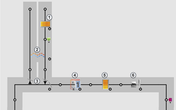
Configuration
The air system is comprised of 6 main components.
- A preheat coil
- A heat exchanger
- An outdoor air controller
- A cooling coil
- A heating coil
- A supply fan
Preheat Coil
If a preheat coil is present, the following assumptions are made.
- It is located before the heat exchanger (if present) to prevent any frost issues.
- The coil entering air temperature is equal to the design day temperature.
- The coil leaving air temperature is 4°C.
- If the coil is a hot water coil, it is assumed that hot water is supplied at 60°C with a return temperature of 43.33°C.
Heat Exchanger
The heat exchanger has the following assumptions.
- The heat exchanger controls the bypass air ratio, per the needs of the system-requested supply air temperature at a given timestep.
| Heat Exchanger Type | ||
|---|---|---|
| Sensible | Enthalpy | |
| Sensible effectiveness at 100% heating air flow | 0.76 | 0.76 |
| Sensible effectiveness at 75% heating air flow | 0.81 | 0.81 |
| Latent effectiveness at 100% heating air flow | 0 | 0.68 |
| Latent effectiveness at 75% heating air flow | 0 | 0.73 |
| Sensible effectiveness at 100% cooling air flow | 0.76 | 0.76 |
| Sensible effectiveness at 75% cooling air flow | 0.81 | 0.81 |
| Latent effectiveness at 100% cooling air flow | 0 | 0.68 |
| Latent effectiveness at 75% cooling air flow | 0 | 0.73 |
Outdoor Air Controller
The outdoor air controller has the following assumptions.
- Has an economizer that modulates flow based on a differential enthalpy control.
- Has a bypass around the heat exchanger (if present) when the economizer is active.
- When operating as a DOAS, the unit is 100% outdoor air.
- The system has demand-controlled ventilation (DCV).
Cooling Coil
The cooling coil has the following assumptions.
- The DX coil is single speed with a rated COP of 3.0.
- The sensible-to-latent heat ratio is auto-sized to meet the system needs during sizing.
- The chilled water coil has the following assumptions.
| Property | Value | Notes |
|---|---|---|
| Coil entering air temperature | N/A | Determined by the design day. |
| Coil leaving air temperature | ~11.11°C | Calculated from the air system supply air temperature minus fan heat generated (typically about 1.5°C - 2°C). |
| Chilled water design inlet temperature | N/A | Set by chilled water loop if chilled water coil is used in system. |
| Chilled water design outlet temperature | N/A | Set by chilled water loop if chilled water coil is used in system. |
Heating Coil
The heating coil has the following assumptions.
- The electric resistance heating coil is 100% efficient.
- The furnace heating coil is 80% efficient.
- The hot water coil has the following properties.
| Property | Value | Notes |
|---|---|---|
| Coil entering air temperature | Varied | 4°C with preheat coil, otherwise it is determined by the design day. |
| Coil leaving air temperature | Varied | 12.7778°C if a traditional air system, 15.5556°C if it is a DOAS. |
| Hot water design inlet temperature | N/A | Set by the hot water loop if a hot water coil is used in the system. |
| Hot water design outlet temperature | N/A | Set by the hot water loop if a hot water coil is used in the system. |
Supply Fan
The supply fan can be either constant or variable volume with the following properties.
| Property | Value | Notes |
|---|---|---|
| Pressure rise | 996 Pa | |
| Total efficiency | 0.6 | |
| Motor efficiency | 0.94 | |
| Minimum flow fraction | 0.3 | Only for variable volume fans. |