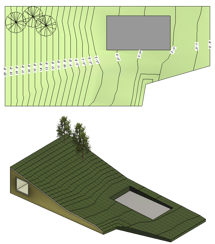
The Toposolid tool defines a topographical element using defined elevation points or imported data.
When viewing and working with a toposolid, consider the following:
- Folding Lines. Folding lines are edges on toposolids. As points are added to create a toposolid, folding lines are automatically created. The folding lines are turned off by default. You can turn them on by selecting them from the Model Categories/Toposolid category in the Visibility/Graphics dialog.
- Maximum Points used: Adjust the maximum number of points used to create a toposolid generated from an imported DWG or a text file. The Revit Ini setting named,
NativeToposolidMaxPointThreshold, controls the number of points that will be used for the toposolid.
- Range from 10,000 - 50,000 points.
- Default value: 20,000
Note: Higher numbers of points used create more accurate toposolid representations, but may impact performance when editing the toposolid or when navigating your model.For additional information see, Misc Settings in Revit.ini.
Toposolid elements can be cut by other elements. Use Cut Geometry in a Family to perform boolean operations to shape toposolids. Use Split Elements to split a toposolid into multiple toposolid elements.
- Site components
- Parking
- Railings
- Floor Based elements
Slab edge families can be applied to the edge of a toposolid. For example a slab edge might be used to model a curb edge on your site.
Toposolid elements support surface patterns used by the material assigned to the toposolid. See About Fill Patterns for Material Graphics for additional information on defining a surface pattern to a material.

Sample toposolid in a site plan and 3D view
