To create a sloped surface, draw a slope arrow or edit the properties of the boundary lines of the surface.
Edit the boundary of the element in a plan view or a 3D view. Then use one of the following methods:
- Slope arrow: Draw a slope arrow on the element. Use slope arrow properties to further define the slope.
- Boundary line properties: Define the slope of the surface by changing properties of its boundary lines.
How slope properties are measured
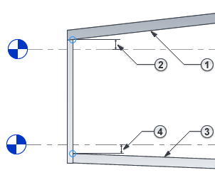
Slope-related properties are measured from the bottom face or top face of the element, depending on the type of element:
- For roofs, ceilings, and soffits, slope-related properties are measured from the bottom face.
 For example, Height Offset From Level specifies the distance between the level and the bottom face of a roof.

- For floors and structural floors, slope-related properties are measured from the top face.
 For example, Height Offset From Level specifies the distance between the level and the top face of a floor.

Modeling multiple slopes
With the exception of roofs, elements can slope in one direction only. To create a surface with multiple slopes, create multiple elements, each with its own slope. Then align and lock the elements together.
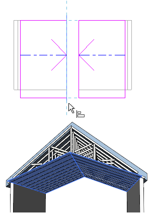
Example
The following images show a cathedral ceiling consisting of 2 surfaces, each with its own slope.