
DXF Import Data
Description
This form is used to select layers when importing Autodesk® AutoCAD Exchange (DXF) files. AutoCAD Exchange files can be used to import structure, design line and section coordinate data.
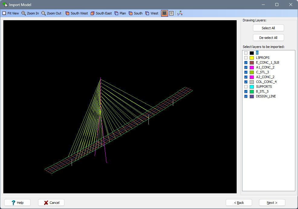
Import Model
All of the layers in the DXF are presented. The program will scan the selected layers for LINE entities, which it will read in as beam members, and for 3DFACE and SOLID entities, which it will read as finite elements. All other entities are ignored.
Import Design Line
All of the layers in the DXF are presented. Only one layer may be selected for import. Only LINES, POLYLINES and ARCS may be imported as sections of a design line. For entities to be imported as a design line they must satisfy the following criteria.
- Must be a LINE, POLYLINE or ARC.
- Must be on the selected layer.
- Must be connected to the other entities that make the design line. The first entity in the DXF file is imported and all subsequent entities must have a direct or indirect connection to this entity.
- The angles at the connecting endpoints of two entities must match (to a tolerance of 1 degree).
- POLYLINES are imported as transient segments. The points must be arranged to give a non-intersecting, strictly increasing polyline.
- If the imported layer consists entirely of LINES then a transient segment shall be created. The points must be arranged to give a non-intersecting, strictly increasing transient segment otherwise the data will be discarded.
Import Shape/Import Section
All of the layers in the DXF are presented. Shapes may be imported as combinations of LINES, POLYLINES and ARCS. For shapes to be imported they must satisfy the following criteria.
- Must be made entirely of LINES, POLYLINES and ARCS.
- Must be closed.
- Must not have any intersections.
CIRCLES may also be imported as separate entities.
When importing a section via the 'Import File' menu item, bars and tendons are identified and imported. When importing shapes via the Define Section form, bars and tendons are identified and discarded.
- Bars are identified as circles of less than 100mm.
- Tendons are identified as two intersecting lines in a + shape. Both lines must be of a length less than 100mm.
Form Graphic
Field Help
Graphics Toolbar
Allows the graphics display to be manipulated.
Drawing Units
Allows the user to select the units that the drawing file will be imported in. This option does not appear on the form when importing a structure.
Drawing Layers
Allows the user to select the layers that are required for import. Only one layer may be selected when importing a design line. The base layer is selected by default.