
Analysis Graphic - General Toolbar
Description
This side toolbar allows the user to define what annotation, axes sets and node positions are to be shown in the graphic view of the structure.
Outline Procedure
Click on the General tab on the right hand side of the graphic window. This toolbar will fly out.
Check one or more of Joint, Member or Result boxes to identify the items to be annotated. Pick the appropriate Format box to open the Text Setup Form to define and format the text to be applied to those items.
Check the boxes and set the fields for Show Global Axes, Show Local Axes, Show Nodes, Transparent Model, Grid, Coordinates and Filtered Members only.
Only those selections that can be applied in a given context are shown.
In the special case of Assign Section Data a 'Switch' button allows the 'Annotation: Member' field to be changed to 'Annotation: Section Data Set' and vice versa.
 Pin / Unpin
If the toolbar is 'pinned' (icon vertical) then it permanently occupies a fixed area of the Graphics Window.
If the toolbar is 'unpinned' (icon horizontal) when the cursor moves beyond toolbar area then the toolbar is minimized into the side status bar containing the General tab. Only the General tab is visible and the screen area formerly occupied by the General Toolbar is occupied by the Graphic Window. If the cursor is placed over the General tab then the Toolbar is maximized and remains active until the cursor moves off it.
A left click on the pin icon toggles between 'pinned' and 'unpinned'.
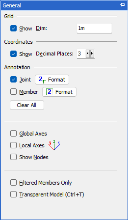
General Toolbar Graphic
Field Help
Grid: Show
Check this box to show a regular grid of points.
Grid: Dim
This field sets the grid size, i.e. the separation of the rows of points in the grid.
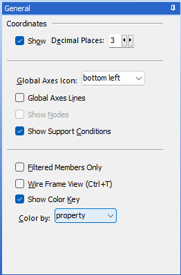
Coordinates: Show
Check this box to show the coordinates of the cursor position.
Coordinates: Decimal Places
This field defines the number of decimal places for the coordinates of the cursor position.
Annotation: Joint
Check this box to show joint numbers.
Annotation: Member
Check this box to show member/element numbers.
Annotation: Result
Check this box to show result values.
Annotation: Format
Click on one of these buttons to display and move focus to the Text Setup form appropriate to the item being considered. Changes made to the text for one type of item do not affect the text for other types of item.
Switch to Member No.
Switch to Struc. Prop.
One or other of these buttons is displayed in the special case of Assigning Basic Structure Properties only. They allow 'Annotation: Member' field to be changed to 'Annotation: Struc(ture) Prop(erty)' and vice versa.
Annotation: Clear All
Clears all check boxes, removing annotation.
Global Axes
Check this box to show the global axes icon. The 3D Elements View has the additional option to show global axes lines.
Local Axes
Check this box to show the local axes set for every member/element.
Show Nodes
Check this box to show a dot at every node position.
Show Support Conditions (3D Elements View only)
Check this box to show graphical representations of the support conditions below each support.
Filtered Members only
Check this box to show only those members that are included in the current Member Selection Filter.
Transparent Model / Wire Frame View (Ctrl-T)
Removes the rendering on Finite Elements, showing only their edges. Always inactive in the Tabular Results form.
Show Color Key (3D Elements View only)
A color key can be shown when Color by is set to sub model or property. This key will assist in matching the color of the sub model group or property group to the name of the group.
Color by (3D Elements View only)
Select one of the following options to change the color scheme for the 3D elements:
| Element | Description |
|---|---|
| sub model | Each 2D or 3D sub model is shown in a different color. |
| property | The color scheme is shown according to the assigned structure property. |
| elasticity | The color scheme is based on member elasticity. |
| member | Each member is shown in a different color. |