Finite Element Geometry
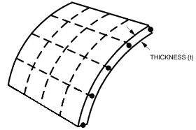
A shell element is a small portion of a continuous shell structure. The thickness of the shell must be small compared to typical lengths over the surface.

Hence the following key assumptions can be made:
- Each element is flat.
- There is no direct stress perpendicular to the plane of the shell.
- There is no shear deformation perpendicular to the plane of the shell.
The shape of a finite element is determined by the position of its nodes. A simple flat shell element is defined merely by its connections to three nodes (triangular element) or four nodes (quadrilateral element). The nodes of a triangular element can be in any order. The nodes of a quadrilateral element are in cyclic order (usually counter clockwise). The four nodes of a simple flat quadrilateral element must lie in a single plane.
Mesh
In order to model a shell structure it is necessary to design a finite element 'mesh'. In order to design a mesh that will accurately model the real structure the following points must be considered:
i) Fineness of mesh

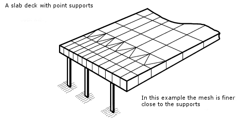
The change in stress within a single element must be small. Consequently the mesh should be finer for areas of the structure in which the stress changes rapidly.
ii) Shape of elements

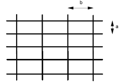
Finite elements should be as near as possible square (quadrilateral) or equilateral (triangular elements). For good results the length of the element should not be greater than 2.5 times the width. The aspect ratio b/a should be less than 2.5.
iii) Use of triangular elements
Triangular elements should be used as rarely as possible and certainly away from areas in which the stress changes rapidly. Triangular elements are principally used to change the fineness of a mesh (see the example for point i above), or to eliminate highly skewed elements.
iv) Sharp Corners

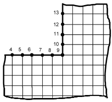
In each finite element the strain distribution is approximated by simple polynomials. The stresses within a finite element are then calculated from the strain. The finite element method will not find the peaks of stress which occur at sharp corners of a structure. In this example it can be expected that good estimates of the stress will be obtained for nodes 4 to 8 and 10 to 13. The stress peak at node 9 will be under-estimated.
