3.5 Crack Width and Stress Calculations for an RC Section
Subjects Covered
- SLS Limiting stresses
- Defining Load Effects
- EN1992-1-1
- Interpolation between long and short term modulus
- Maximum crack widths
- Crack widths between specific bars.
Outline
The calculation of Serviceability limit state stresses and maximum crack widths are to be calculated for the edge section, with reinforcement defined in section 3, under two load/design situations.
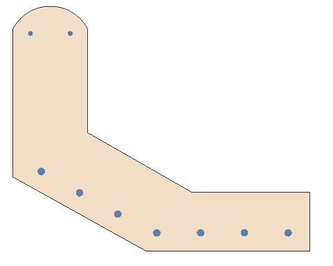
Design situation 1
- The precast beam is lifted at its ends through the centroid of the section which generates a nominal My bending moment of 218kNm due to the dynamic effect on its self weight. Check that the concrete and steel stresses do not exceed the SLS limits using the characteristic combined capacity.
- Check the crack widths for this design situation using the SLS Frequent Combination of actions (not normally a requirement for this design situation but shown for completeness).
Design situation 2
- When the section is attached to the cast in place slab the Neutral axis is forced to be horizontal. The dead load nominal moment is 126kNm (SLS Gamma= 1.0) and the live load moment is 254kNm (SLS Gamma= 1.0). What are the concrete & reinforcement stresses for this case if an interpolated elastic modulus is used?
- What is the max crack width (clause 7.3.4) for this case.
- What is the crack width (clause 7.3.4) between the two left most bars in the bottom face.
Procedure
- Start the program and use the Home Open button to open the file “My EU Example 3_4a.sam” created in example 3.4.
- Use the menu item File | Titles to change the Sub-title to “Example 3.5” and the Job Number to “3.5”.
- Click on ✓ OK to close the Titles form.
Design Situation 1
Define Load Effects
- The existing Loadcase will be modified by selecting the Loadcases object “SL1: Loadcase” in the Design Section navigation window which will open the Define Loadcase form.
- Select “SLS Characteristic” in the Combination field of the table at the top of the form and select “Var – Leading” in the Permanent / Variable field of the Applied forces, if it is not already set to this. Click ✓ OK to close the Define Loads form.
Calculate Stresses
- From the Design Section navigation window toolbar use the
 dropdown to select Bending, Axial and Shear which will open the appropriate analysis form.
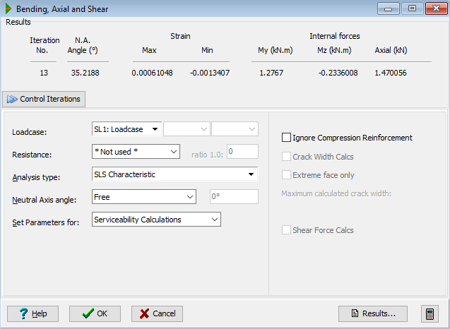
 - Ensure that Analysis type is set to “SLS Characteristic” and select “SL1: Loadcase” in the Loadcase drop down.
- Select “Not used” in the Resistance drop down.
- Select “Free” in the Neutral Axis angle drop down and ✓ OK the error message that may appear as it is just a warning.
| Form | Results |
|---|---|
 |
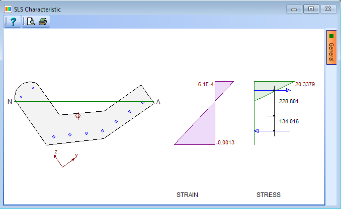 |
- Open the results viewer with the Results button. The tables of Maximum and Minimum Strains show the concrete and steel stresses to be 20.34N/mm² and -219.99N/mm² respectively (we can compare these with the allowable limits of 19.125N/mm² for the concrete and -400N/mm² for the reinforcement showing an overstress in the concrete (as noted in the error message).
- Close the results viewer.
Crack Width Checks
- Select “SLS Frequent” in the Analysis type field and tick the Crack Width Calcs tick box. Note that the crack width is 0.158mm before closing the Bending, Axial and Shear form with ✓ OK.
Design Situation 2
Create a second Loadcase by using the
 icon in the Design Section navigation toolbar and selecting “Loadcase”. Change the name to “Loadcase 2”.
Use the + button near the bottom of the form to add 2 rows to the table.
On the first row of the table, select “Y Moment” from the drop down options in the Type column.
Enter a value of “126kNm” in the Characteristic Effect column.
Select “Perm” from the Category column drop down.
On the second row of the table, select “Y Moment” from the Type column drop down options.
Enter a value of “254kNm” in the Characteristic Effect column.
Select “Var-Leading” in the Category field.
The values in the Serviceability γ column for both rows should be set to “1”.
In the line of data at the top of the form set the Combination to “SLS Characteristic”.
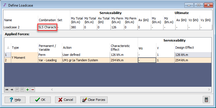
Close the Define Loads form with the ✓ OK button.
Stress Checks
From the Design Section navigation window toolbar use the
 dropdown to select Bending, Axial, and Shear, which will open the appropriate analysis form.
Click ✓ OK.
Click on the Loadcase drop down and select “SL2: Loadcase: 2” from the list.
Again, click ✓ OK on the error message form.
Click on the Neutral Axis angle drop down and select “Fixed horizontal” from the list.
Click on the Resistance drop down and select “Not used” from the list.
Click on the Set Parameters for drop down and select “Serviceability Calculations” from the list. This will open the Design Data for Serviceability Calculations form.
Confirm that the Elastic Modulus Type field is set to “Interpolated” and use ✓ OK to close the form.
Click on the Results button to open the Results Viewer.
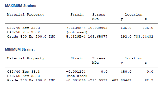
The concrete and reinforcement stresses are shown in the MAXIMUM and MINIMUM Strains table. The concrete stress is 16.94N/mm² and the reinforcement stress is -211N/mm². Close the Results Viewer.
Crack Width Checks
In the Bending, Axial and Shear form select “SLS Quasi-permanent” in the Analysis type field.
This analysis type can be selected because the edge section is now part of the structure and permanent dead loads are being considered combined with live loads.
Tick the Crack Width Calcs tick box and open the results viewer, which shows that the section is uncracked.

Close the Results Viewer and click ✓ OK to close the Bending, Axial and Shear form.
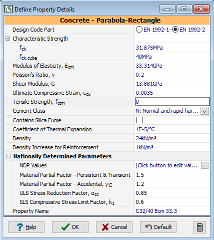
To force the section to crack we can set the tensile strength of the concrete material to zero, but bear in mind that this value will also be used in calculation of the crack spacing – as will be shown in the results
In the Materials navigation window select the “C32/40” concrete property which will open the Define Property Details form.
Set the value of Tensile Strength, fctm to “0” and use ✓ OK to close the form.
In the Design Section navigation window toolbar use the
 dropdown to select Bending, Axial and Shear to analyse again. The maximum crack width is now 0.127mm.
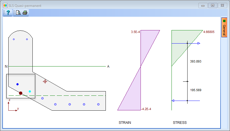
It is also possible to find the crack width between specified bars. We want to find out the crack width between the two outermost bars at the left hand side of the beam.
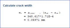
To do this draw a box around the two bars. Open the Results Viewer to display the crack width calculations considering just those bars. The maximum crack for those bars is 0.0597mm.
| Bars | Results |
|---|---|
 |
 |
- Close the Results Viewer and use ✓ OK to close the Bending, Axial and Shear form.
- Use the File | Save As menu item to save the data file as “My EU Example 3_5.sam”.
- Close the program.
Summary
The first design situation considers the lifting of the beam where it will bend about the principle axis. The value of the bending moment is greater than just the dead load bending moment to take into account the dynamic effects of the lifting.
The max concrete stresses can be obtained from the graphics, but the reinforcement stresses can only be obtained from the results output.
The second design situation illustrates the calculation of stresses and crack widths at SLS when some of the load is long term permanent load and the rest is instantaneous live load. The method used is an interpolation between the long and short term modulus so the stresses calculated are those that would occur at the end of the structure life. To check the stresses just after construction, the long term modulus would need to be modified, so as to represent the correct amount of creep, or the user can choose to use the short term modulus only.
