1.1 Setup and Templates
Subjects Covered
- Design Code
- Company Identity
- Templates
- Titles
- Units
- Materials
- Preferences
Outline
Autodesk® Structural Bridge Design may be used numerous times within a project and certain data will be common to all jobs within this project. In fact some data will be common to all projects. Much of this data can be set up by defining templates and setting personal preferences which will stored in template files and the system registry for each user.
In this example we set up the default company information, design code and personal preferences, and then create a number of section, beam and project templates that can be used in further examples given in this manual.
We will create 5 templates:
- A design sections template
- A design beam template for prestressed beams
- A design beam template for steel/concrete composite beams
- A design beam template for reinforced concrete beams
- A basic project template
Procedure
Start Autodesk Structural Bridge Design.
Exit the Home screen using the
ESCkey or the back button

Use the main menu item Options | Design Code to select “Eurocode + UK Annexes”.
Use the menu item Options | Company Identity to open the Set Company Identity form.
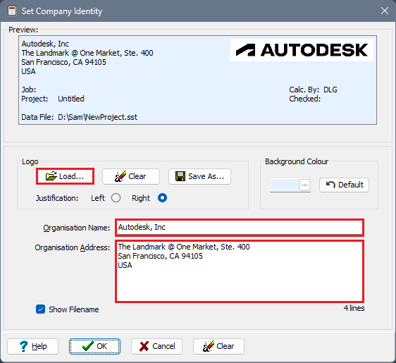
Enter your Organisation Name and your Organisation address.
Click on the Load… button to select a bitmap to display as a logo in the heading of any output that is produced by the program. Browse to the examples folder and select the “Mylogo.png” file. Alternatively use your own logo.
Click on ✓ OK and confirm that the changes should be saved.
Open the Preferences form using the menu item Options | Preferences and on the General tab ensure that the tick box on the form is ticked so that an overview is always provided.
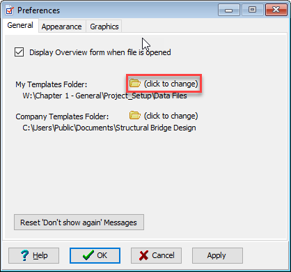
Note the default folder name for My Templates Folder and change this if required by clicking on the (click to change) button.
On the “Graphics” tab of the Preferences form, tick the box for Reverse direction of plotted Bending Moments, so that BM diagrams are plotted with sagging moments (Positive) below the beam and switch on Auto Redraw so that graphics displays are automatically updated. Note that the colours used for the chart data series can be defined by the user on this tab.
Click on ✓ OK to close this form.
Open the Edit Units form using the menu item Options | Edit Units. Use the Reset Current Units... button and then change the units for velocity to “m/s”.

By default the unit formatting is set to "General". Format style for individual unit types can be set here, or use the Reset Formatting drop down and select "Default" for alternative format style for all unit types that is applicable for engineering use.
If the unit fields are set on startup before creating a new model or before opening an existing file, the defaults will be saved to the system registry and used as the default for future models. If the unit settings are changed after new project is selected or when an existing model is loaded, then these settings persist when the file is saved.Click ✓ OK to close this form.
To create a Design Section Template follow the following steps:
a. Use the menu item File | New | Single Design Section
b. Use the menu item File | Titles to open the Titles form.
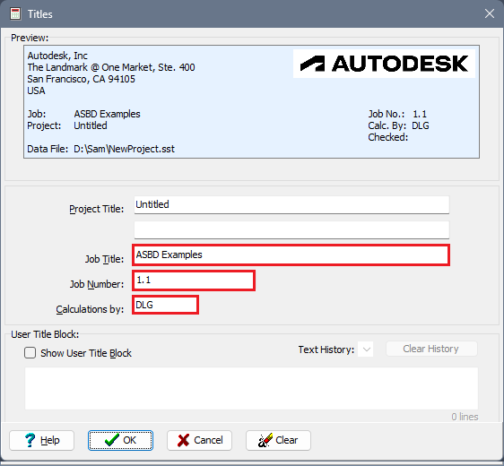
c. Set the Job Title field to “ASBD Examples” and set the Job Number to “1.1”.
d. Enter your initials in the Calculations by field.
e. Click on ✓ OK to close this form.
f. At the bottom of the left hand side navigation pane, ensure that the Materials group is selected.

g. Create a concrete material by clicking on the + button at the top of the navigation window and select Concrete – Parabola-Rectangle. By default this concrete has a characteristic cube strength of 50N/mm² which is grade C40/50 concrete. Change fck,cube to “40MPa” (40N/mm²) and then click on the ✓ OK button to accept this material.
h. Create a second Parabola-Rectangle concrete material with + in the same way as the first, but accept the characteristic cube strength of “50MPa” (50N/mm²). Click on ✓ OK to accept.
i. Create a Reinforcing Steel – Inclined material by using the + button. Set k to be “1.08” and Characteristic Strain Limit to “0.05” (the upper bound limit given in Table C.1 of EN 1992-1-1, Annex C for class B ductility). Click on ✓ OK to accept.
j. Create a Prestressing Steel – Inclined material, setting the Relaxation Class to “Class 2” if not already set. The default values for strength relate to strand type Y1860S7 from EN 10138-3 so we will accept all other default values. Click on ✓ OK to accept.
k. Create a Structural Steel material using the default values. Click on ✓ OK to accept.
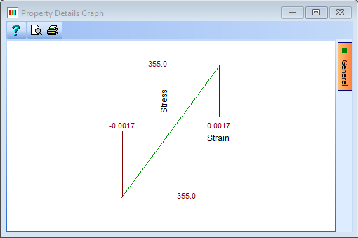
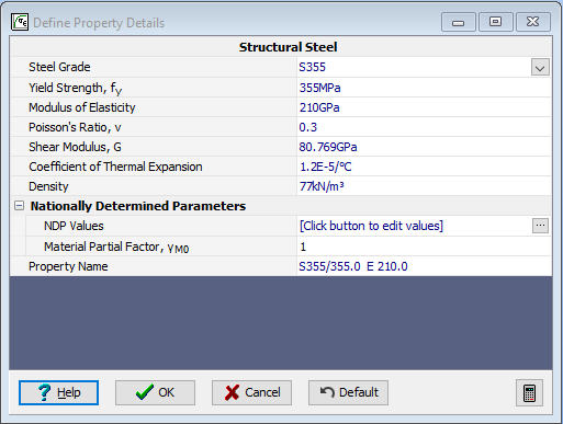
l. Save this data to a template using the menu item File | Save As Template | My Template with the filename “EU Section.sbt”
Repeat the above steps from “a” to “l”, using exactly the same materials and settings for each of the following; saving the templates with the names in parenthesis:
- File | New | Single Design Beam | Steel Composite (EU Steel Composite.sbt)
- File | New | Single Design Beam | Pre-tensioned Prestressed (EU Pretensioned.sbt)
- File | New | Single Design Beam | Reinforced Concrete (EU RC.sbt)
- File | New | Blank Project (EU Project.sbt)
Close the program.
Summary
The templates created in this example may be used as default values when any new section, beam, or project is started. Of course this data may be changed locally at any time to reflect local requirements without affecting the saved template settings. For example, the default value for the Ultimate Compressive Strain limit, εcu, is set to 0.0035, which is ok for sections in flexure, but we would need to alter this to 0.002 if the section or component under consideration was mainly in compression.
These templates can be saved as global company templates by saving them into the “Company Templates” folder which should be a locally shared folder or a mapped network drive folder.
The section or beam templates will relate to a single section or beam but a “project” may contain a single structure together with any number of sections and/or beams, either linked or embedded. A linked design section or beam is a single section or beam, saved as a standalone file, which can be linked to multiple projects to allow for re-use.
One or more (embedded) design sections or beams can be created within a project rather than linked to an external file.
