Activity 1: Create a T-Spline box
To create a T-Spline model of the utility knife, start with a T-Spline box with a reference image in the center of the box.
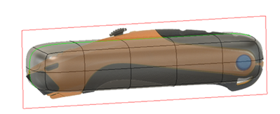
Reference image, with a box T-Spline form
Steps
Select the utility knife image as a canvas on the XY plane.
- Select the Right face of the ViewCube, so the Y-axis points to the right, and Z-axis points up.
- Select Solid > Insert > Canvas.
- Select the YZ plane.
- Select the image button on the Canvas dialog.
- Navigate to the folder containing the utility knife and select the file UtilityKnife.png and click Open.

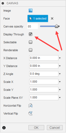
Adjust the canvas settings to a opacity of 85 and Display Through.
- Check Display Through to ensure the canvas is seen through the T-Spline form.
- Set the Canvas Opacity to 85.
- Ensure the utility knife canvas is oriented with the blade end of the knife to the left. If the knife is not oriented correctly, use the rotate manipulator to orient the knife.
- Click OK.
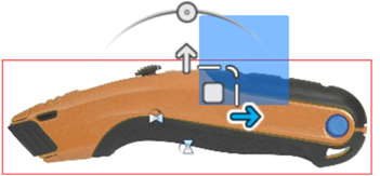 Note: The image is placed on the canvas, but it may not be the correct size. In the next step, the canvas is scaled or calibrated to the correct size.
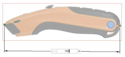
Calibrate the image to 180 mm for the length of the utility knife.
- In the Browser, click the drop-down arrow next to the Canvases folder.
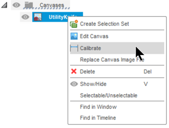
- Right-click on UtilityKnife and select Calibrate.
- Select the Right face of the ViewCube, so the Y-axis points to the right, and Z-axis points up.
- Click once on the furthest left point on the knife.
- Click once on the furthest right point on the knife.
- Enter 180 mm in the length field and hit enter.
- Zoom out as necessary to see the entire model.


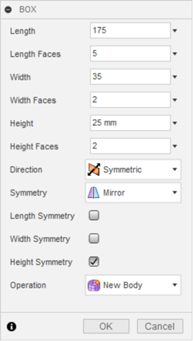
Create a box with the dimensions of 175 mm, 35 mm, 25 mm, that is symmetric, mirrored by the height, and with 5 length faces.
- Click Solid > Create > Create Form, to open the Form tab.
- Click Form > Create > Box.
- Select the Right face of the ViewCube, so the Y-axis points to the right, and Z-axis points up.
- Select the YZ plane as the plane to create the box.
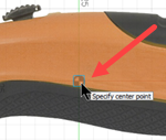
- Select Center as the Rectangle Type, in the Box dialog, then click the center of the plane.
- Drag the mouse to size the rectangle to about the same size as the canvas and click to set the initial size.
- Set the box's Length to 175 mm, Width to 35 mm and Height to 25 mm.
- Set the Length faces to 5, and the Width and Height faces to 2.
- Set the Symmetry to Mirror, and check Height Symmetry, in the Box dialog.
- Click OK to finish the box.



Activity 1 summary
In this activity, you inserted an image as a canvas to use as a reference for creating a T-Spline form. You then scaled the canvas to be the correct size. Finally, you created a T-Spline box primitive shape as a starting point for creating your form.
