
Steep and Shallow reference
This feature is part of an extension. Extensions are a flexible way to access additional capabilities in Fusion. Learn more.
Steep and Shallow is a finishing strategy that machines steep areas using Contour passes and shallow areas using Parallel or Scallop passes.

- Contour passes applied to steep areas
- Scallop passes applied to shallow areas
- Complete Steep and Shallow toolpath
Use this strategy on parts that consist of steep areas and shallow areas in their geometry, for example, parts with 3D freeform surfaces.
Using this strategy saves you time by generating a toolpath for both steep and shallow areas and also incorporates a range of controls to allow machining of both steep and shallow regions efficiently.
Manufacture > Milling > 3D > Steep and Shallow ![]()
Types of shallow passes
In Steep and Shallow, you have the choice of two types of passes to use for shallow areas:
- Parallel passes are side by side and run in a defined direction along or across the surface. Selecting Parallel allows you to specify a clearance by which the tool stays away from connecting steep walls to avoid contacting or rubbing against them.
- Scallop passes are offset-inwards from an outer profile. When using Scallop, you can generate a continuous toolpath that has fewer tool-lifts between passes, which provides a better surface finish.
- Parallel passes on a shallow area
- Scallop passes on a shallow area
Defining steep areas and shallow areas of the model
Use a Threshold Angle, calculated from the horizontal plane, to specify which areas of the model are defined as steep areas and which areas are defined as shallow areas.
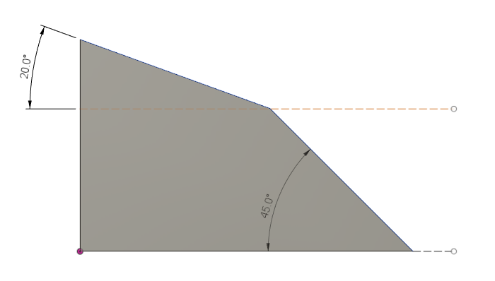
Specifying a Threshold Angle greater than 20 degrees, but smaller than 45 degrees, will define the area of the 20-degree slope as shallow and therefore apply shallow passes to that area.
To cover the 20-degree area entirely with shallow passes, the Threshold Angle must be slightly bigger than 20 degrees to account for any tolerance issues.
For example, a Threshold Angle value of 21 defines every area with a slope under 20 degrees as a shallow area.
Using a Threshold Angle of 21 degrees gives:
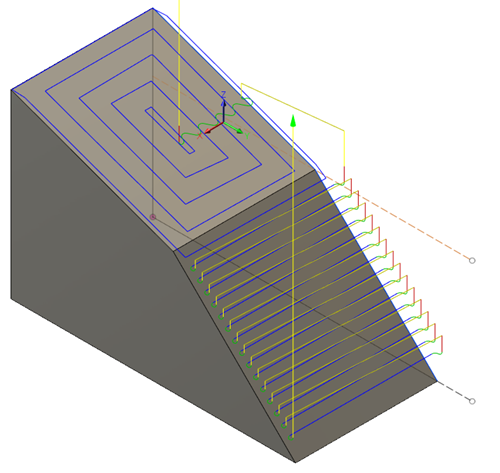
The area with the 45-degree slope has a greater angle than the Threshold Angle value and is therefore defined as a steep area, which has Contour passes applied to it.
Using a Threshold Angle of 46 degrees gives:
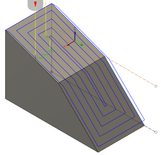
As the slopes of the areas are lower than the Threshold Angle, all areas are defined as shallow areas and therefore have Scallop passes applied to them.
Using a Threshold Angle of 19 degrees gives:
As the slopes of the areas are greater than the Threshold Angle, all areas are defined as steep areas and therefore have Contour passes applied to them.
Improving surface finish
Use Overlap Distance, Wall Clearance, Smooth Offsets, Remove Cusps at Junctions, and Continuous to help improve the surface finish of a part.
Overlap Distance
Use Overlap Distance to specify a distance over which steep and shallow passes extend and apply over each other to blend between the two areas to provide a better surface finish.
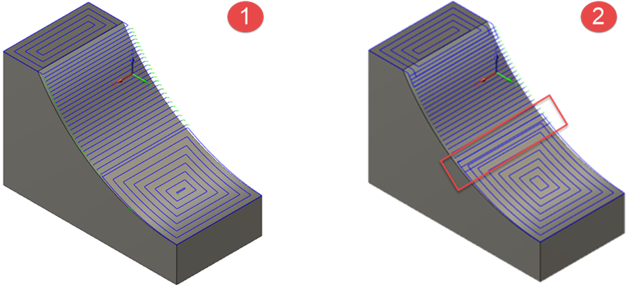
- Steep and Shallow strategy applied with no Overlap Distance
- Steep and Shallow strategy applied with an Overlap Distance of twice the Stepover value.
Wall Clearance
When machining shallow areas that are close to steep walls, the tool or shaft can rub on the surrounding wall geometry and cause dwell marks.
To reduce the risk of dwell marks, and improve the surface finish of the part, use Wall Clearance to specify the distance the shallow passes stay clear from any nearby steep walls.
This option is available only when using Parallel passes for shallow areas.
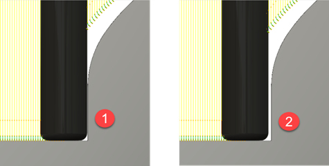
- A Wall Clearance of 0mm
- A Wall Clearance equal to the Stepover value (0.3mm)
Smooth Offsets
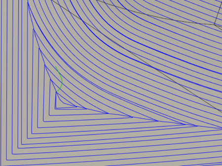
When using Scallop passes over shallow areas, the geometry of the outer profile can generate sharp corners in the toolpath as it offsets inwards. The sharp corners can cause the tool to slow down noticeably, which changes the axial forces, radial forces and deflection conditions on the tool which may result in dwell marks around the sharp corners.
Select Smooth Offsets to help the tool glide smoothly over the part by replacing any sharp corner turns of a toolpath with a curved, smoother motion.
- Smooth Offsets (option cleared)
- Smooth Offsets (option selected)
Remove Cusps at Junctions
When using Scallop passes over shallow areas, the geometry of the outer profile can generate sharp corners in the toolpath as it offsets inwards. The distance between the apexes of the sharp corners becomes greater than the programmed Stepover value. As a consequence of the larger distance, excess material is left behind between the passes around the apexes in the form of cusps.
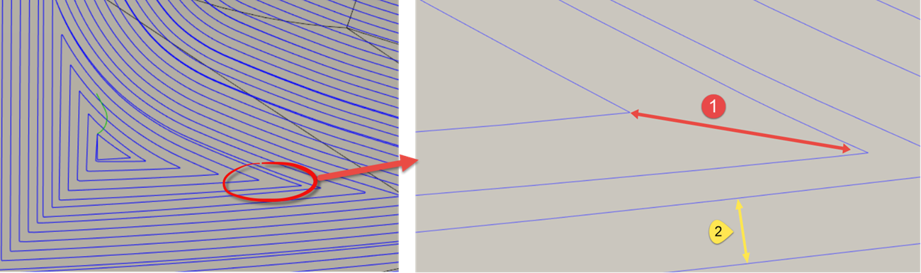
- Stepover distance between apexes
- Programmed Stepover
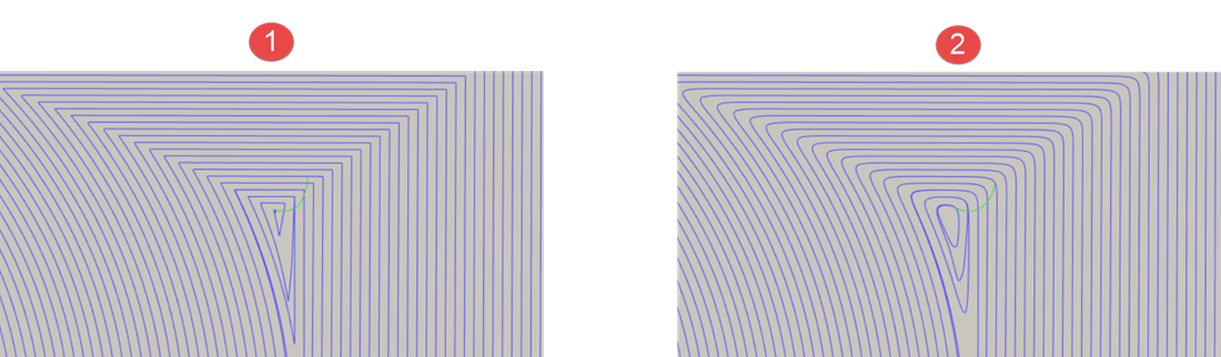
To prevent cusps appearing for a better surface finish, use Remove Cusps at Junctions. Selecting this creates an extra pass that runs through the apexes to remove any tiny cusps of material that are left behind.
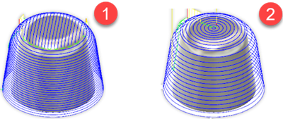
Continuous
Use Continuous to improve the part's surface finish by removing any steps between consecutive passes in steep and shallow areas. This is achieved by replacing any closed, toolpath contours with a continuous spiral-style toolpath. This results in minimal tool-lifts and reduced cycle time.
For shallow areas, this option is available only when Scallop passes are specified.
Shallow passes:
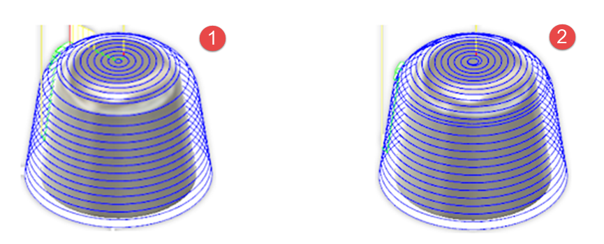
- Continuous (option cleared)
- Continuous (option selected)
Steep passes:
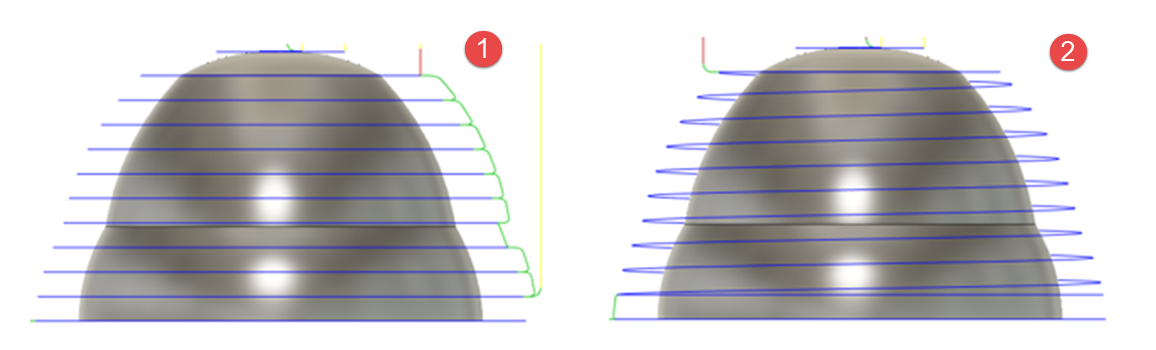
- Continuous (option cleared)
- Continuous (option selected)
Reducing machining time
When machining shallow areas using Parallel passes, the strategy analyzes the shallow areas on the model to calculate an optimal angle to use for the Parallel passes. Using an optimal angle reduces the length of the toolpath, which results in faster machining times.
Safer ordering for machining steep walls
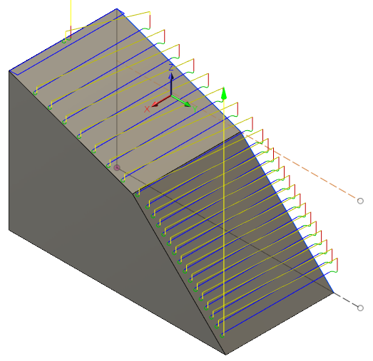
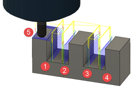
When machining a model with Steep First selected as priority:
1 - 4 — Each steep wall is machined in its entirety before moving onto the next.
5 — All shallow areas are machined once steep walls have been completed.
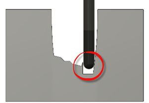
However, in some cases, if there is uneven stock material left from previous operations between two steep walls, cutting to a large depth on just one of the steep walls creates a heavy load on the tool as it interacts with left-over material around it. It is better to cut alternately between the two steep walls to avoid damaging the tool.
Maximum Remaining Stock is used to reorder the toolpath such that two steep walls near each other are machined at the same Z-level before proceeding to the next Z-level. Estimate a value depending on the tool geometry and the distance between two steep regions.
A Maximum Remaining Stock value of 2mm, does not reorder the machining passes on steep walls. Each wall is still machined in its entirety before moving onto the next.
A Maximum Remaining Stock value of 10mm, does reorder the machining passes. Steep walls in proximity to one another are machined at the same Z-level before proceeding to the next Z-level, providing a safer order.
Safer tool conditions on approach to and on leaving a cutting move
When machining horizontal or shallow surfaces, to avoid causing any surface finish issues on the part, it is appropriate to enter and leave a cutting move vertically.
Likewise, when machining vertical or steep walls, it is appropriate to enter and leave a cutting move horizontally.
However, as the steep and shallow strategy machines both, steep and shallow areas in one strategy, you cannot use either vertical or horizontal lead-moves only, instead, steep and shallow uses lead-moves that always enter and leave a cutting move in the direction that is normal to the surface.
Entering into a cutting move from the direction that is is normal to the surface of the part provides a better way to engage the stock at the beginning and end of a cutting move for both, steep and shallow areas.
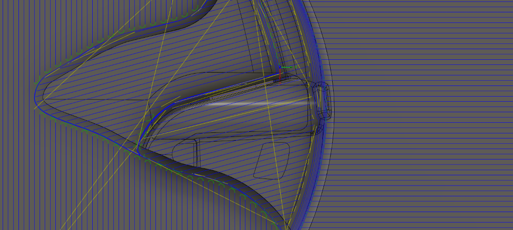
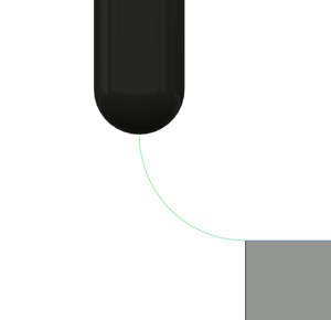
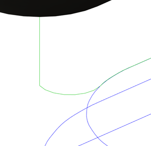
Example of the construction of a lead-in move in Steep and Shallow:
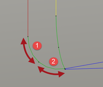
1 - Vertical arc
2 - Surface normal arc