Create a 4-axis toolpath
This feature is part of an extension. Extensions are a flexible way to access additional capabilities in Fusion. Learn more.
On the Manufacture workspace toolbar, select a 3D operation. For example, click Milling > 3D > Scallop.
The Scallop dialog opens.
On the Multi-Axis tab, from the Machining Type group, select 4-axis.

Rotary Axis, Tool Axis, and Collision Avoidance settings appear in the Multi-Axis tab.
Set the orientation of the rotary axis. From the Rotary Axis group, select an option from the Rotary Axis drop-down menu. For example, select Setup X Axis if you have set the X axis of your Setup to match the rotary axis in your machine tool.
Set the rotary axis location by selecting an option from the Origin drop-down menu. For example, if you have set the origin of your WCS in your Setup to match the center of the rotary axis in your machine tool, then select Setup WCS origin.

In the Tool Axis group, select an option from the Primary Mode drop-down menu that best suits your machining requirements. For example, To Rotary Axis orients the tool such that it is always pointing towards the rotary axis.
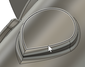
On the Geometry tab, you may want to contain the toolpath area with a Machining Boundary and then select the face, edge, or sketch that represents the area to be machined. If no selection is made, the entire model will be evaluated for machining within the defined Stock box.
On the Heights tab, adjust the Clearance Geometry if needed. By default, a plane is used for the clearance geometry.
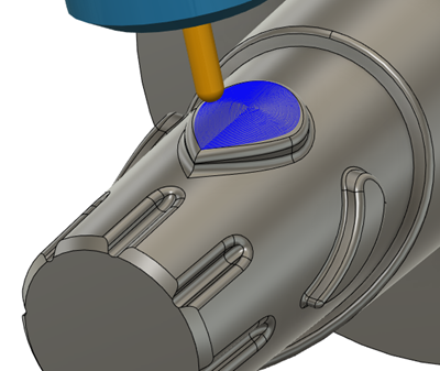
Program the remainder of the toolpath and then click OK.
The 4-axis toolpath is generated.